Hydraulic driving system, base plate and mechanical traveling device

A drive system, hydraulic technology, used in control devices, transportation and packaging, vehicle components, etc., can solve problems such as complex layout and inconvenient operation

Active Publication Date: 2012-10-17
SANY HEAVY IND CO LTD (CN)
View PDF9 Cites 4 Cited by
  • Summary
  • Abstract
  • Description
  • Claims
  • Application Information

AI Technical Summary

Problems solved by technology

[0006] In view of this, the present invention aims to propose a hydraulic drive system, chassis and mechan...

Method used


Image

  • Hydraulic driving system, base plate and mechanical traveling device
  • Hydraulic driving system, base plate and mechanical traveling device

Examples


Embodiment Construction

[0025] In order to enable those skilled in the art to better understand the technical solutions of the present invention, the present invention will be further described in detail below in conjunction with the accompanying drawings and specific embodiments. It should be pointed out that the description and sequence of specific structures in this section are only descriptions of specific embodiments, and should not be considered as limiting the protection scope of the present invention.

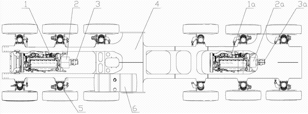
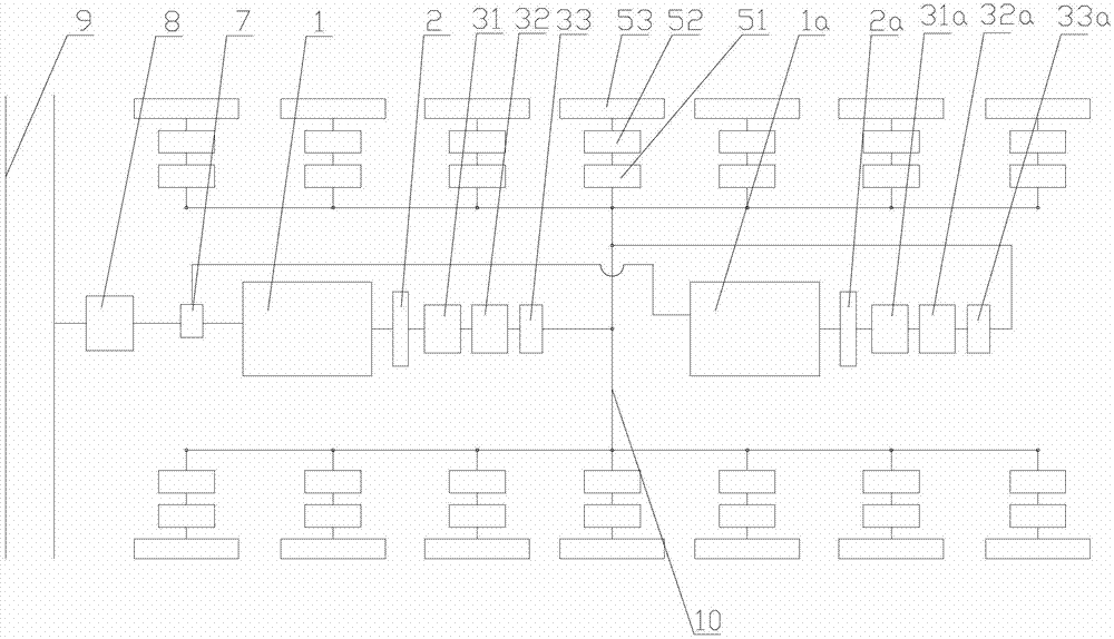
[0026] The present invention provides a hydraulic drive system, including: a multi-power system, the multi-power system includes a plurality of power sources and a driving oil pump group connected to each power source, and the driving oil pump group is used to transfer the power provided by the power system converted into hydraulic driving force; the power composite oil circuit is used to compound the hydraulic driving force of the driving oil pump group connected to each power source to the ma...


PUM


Abstract

The invention relates to the technical field of engineering machines, and discloses a hydraulic driving system, a base plate and a mechanical traveling device. The hydraulic driving system comprises a multi-power system, a power composite oil path and traveling units, wherein the multi-power system comprises a plurality of power sources and a driving oil pump group which is connected with each power source, and the driving oil pump groups are used for converting power provided by a power system into hydraulic driving force; the power composite oil path is used for compounding the hydraulic driving force of the driving oil pump groups which are connected with the power sources to a main oil path; and the traveling units are connected with the power composite oil path and are driven to travel by the hydraulic driving force. According to the hydraulic driving system, power of the multi-power system is converted into the hydraulic driving force, and each traveling unit is driven to move by utilizing the hydraulic driving force, so that each traveling unit can be driven to travel; and the integral driving system is stable in motion, simple in layout of an integral pipeline and convenient to operate, and infinitely variable speed is realized.

Description

technical field [0001] The invention relates to the technical field of construction machinery, in particular to a hydraulic drive system, a chassis installed with the hydraulic drive system and a mechanical traveling device with the chassis. Background technique [0002] At present, many mechanical traveling devices are mechanically driven by engines, and the engines and their mechanical driving devices are arranged on the chassis of the mechanical traveling devices. [0003] At present, most of the chassis of large-tonnage special-purpose engineering vehicles produced by domestic and foreign automobile companies use a single engine as the power source, and the transmission system adopts mechanical transmission. [0004] A single engine is used as the power source, and the mechanically driven chassis will be driven by multi-stage gears and shifting mechanisms, which will make the chassis with the transmission system heavy, and the braking and steering control systems will be...

Claims


Application Information

Patent Timeline
IPC IPC(8): B60K17/10B60K17/28
Inventor 杨平易秀明黄辉阳
Owner SANY HEAVY IND CO LTD (CN)
Why Eureka
Try Eureka