Washing machine dewatering device and washing machine

A drainage device and washing machine technology, applied in the washing machine field, can solve the problems of increasing the energy consumption of the washing machine, affecting the life of the washing machine, loud noise, etc., and achieve the effects of avoiding bacterial growth, simple structure, and low cost

Inactive Publication Date: 2012-10-17
QINGDAO HAIER WASHING MASCH CO LTD
View PDF2 Cites 31 Cited by
  • Summary
  • Abstract
  • Description
  • Claims
  • Application Information

AI Technical Summary

Problems solved by technology

[0006] But the structure of the washing machine mentioned above, after draining, because the rubber balls or flexible particles are in a state of free scattering in the barrel, a lot of noise...

Method used


Image

  • Washing machine dewatering device and washing machine
  • Washing machine dewatering device and washing machine
  • Washing machine dewatering device and washing machine

Examples


Embodiment 1

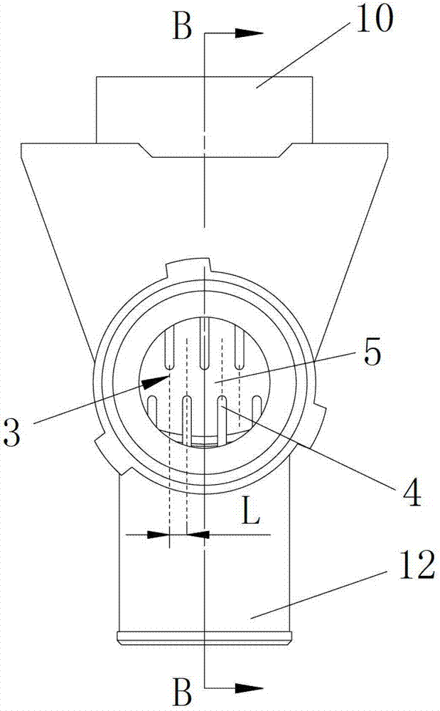
[0037] Such as figure 2 As shown, the two sets of comb structures described in this embodiment are arranged up and down oppositely, with a transverse fracture 5 between them, and the extension line of the retaining ribs 4 of the upper set of comb structures and the retaining ribs 4 of the lower comb structure in turn Alternate vertically, the straight lines where the retaining ribs 4 of the two sets of comb structures are parallel, and the distance L between two adjacent straight lines is the same. The fracture of this structure is set in the middle, which is not only beneficial for the scraps scraped by the retaining ribs to slide and slide through with the drainage water flow, but also facilitates the passage of flakes such as coins.

Embodiment 2

[0039] The retaining ribs described in this embodiment are inclined or curved from the edge of the barrier to the fracture along the water outlet direction, and all the inclined or arc-shaped bending of the retaining ribs constitute a concave diversion structure for the filter facing the drainage chamber. The retaining rib described in this embodiment is an inclined or arc-shaped curved structure as a whole.

Embodiment 3

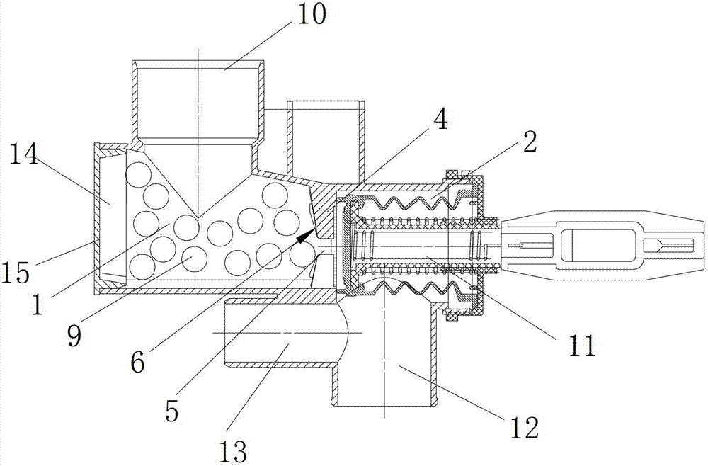
[0041] Such as Figure 3 to Figure 5 As shown, the ribs described are sheet-like structures, and the width of the side walls along the water flow direction is greater than the width of the side walls of the corresponding particle storage chamber, and all the ribs correspond to the side walls of the particle storage chamber from the edge of the barrier to the The fracture is inclined or curved to form a diversion structure that is concave toward the drainage chamber of the filter. The side wall of the retaining rib in this embodiment close to the particle storage chamber is an inclined or arc-shaped curved structure.


PUM


Abstract

The invention discloses a washing machine dewatering device and a washing machine. The washing machine comprises an outer barrel, an inner barrel and a wave wheel, wherein cleaning particles for cleaning the walls of the barrels are arranged between the inner barrel and the outer barrel, the dewatering device comprises a particle charging and discharging cavity for containing the cleaning particles during dewatering and automatically putting the cleaning particles between the inner barrel and the outer barrel to clean the walls of the barrels due to the buoyancy force when water enters and a dewatering cavity, and a filtering structure which baffles the cleaning particles and discharges line scraps and smaller impurities is arranged between the particle charging and discharging cavity and the dewatering cavity. The filtering structure comprises a particle baffling part, a filtering gap and a fracture crossed with the filtering gap, wherein the fracture is communicated with the filtering gap, so that the line scraps wound on the baffling part is washed by water flow and fallen off to be discharged out of the fracture, and a filtering surface of the filtering structure which corresponds to one side of the charging and discharging cavity is an arc surface/inclined surface flow guide structure which is concave to the other side at the position of the fracture. The washing machine dewatering device and the washing machine disclosed by the invention are simple in structure, and low in low, and prevents bacterial from growing caused by the dewatering blockage and the residual line scraps when the cleaning particles are intercepted.

Description

technical field [0001] The invention relates to the field of washing machines, in particular to a washing machine drainage device and a washing machine. Background technique [0002] There is a closed environment between the inner and outer barrels of the existing washing machine, and only water can pass through. Due to the limitations of the above-mentioned structure of the washing machine and the particularity of the use environment, after 3-5 months of use, the outer wall of the inner barrel and the outer barrel Dirt will adhere to the inner wall, thereby breeding different degrees of bacteria, and most of the bacteria that grow are harmful to the human body. [0003] Along with the raising of people's living standard and the raising of the quality of life requirement, the solution of the hygienic problem of washing machine has shown very urgent. According to the investigation of the internal environment of the washing machine by relevant scientific research institutions...

Claims


Application Information

Patent Timeline
IPC IPC(8): D06F39/08D06F39/10
Inventor 吕佩师李海涛许升邓秀文
Owner QINGDAO HAIER WASHING MASCH CO LTD
Why Eureka
Try Eureka