Pipeline drainage structure

A drainage structure and pipeline technology, applied in underwater structures, infrastructure engineering, water conservancy projects, etc., can solve the problems of reduced runoff, small diameter of the drainage cover, flooding Jinshan, etc., to reduce the probability of blockage, reduce Labor cost, high reliability effect

Inactive Publication Date: 2012-10-17
SHANGHAI DATONG HIGH SCHOOL
View PDF0 Cites 13 Cited by
  • Summary
  • Abstract
  • Description
  • Claims
  • Application Information

AI Technical Summary

Problems solved by technology

[0002] In our life, we often find that the sewer pipes and rainwater pipes are easily blocked due to various debris. For this reason, sanitation workers need to dredge and clean them again and again. In thunderstorms, the water pipes are often difficult to keep up with the drainage demand due to the runoff. On the one hand, the caliber of the sewer cover itself is too small to meet the needs of the ab

Method used


Image

  • Pipeline drainage structure
  • Pipeline drainage structure
  • Pipeline drainage structure

Examples


Embodiment 1

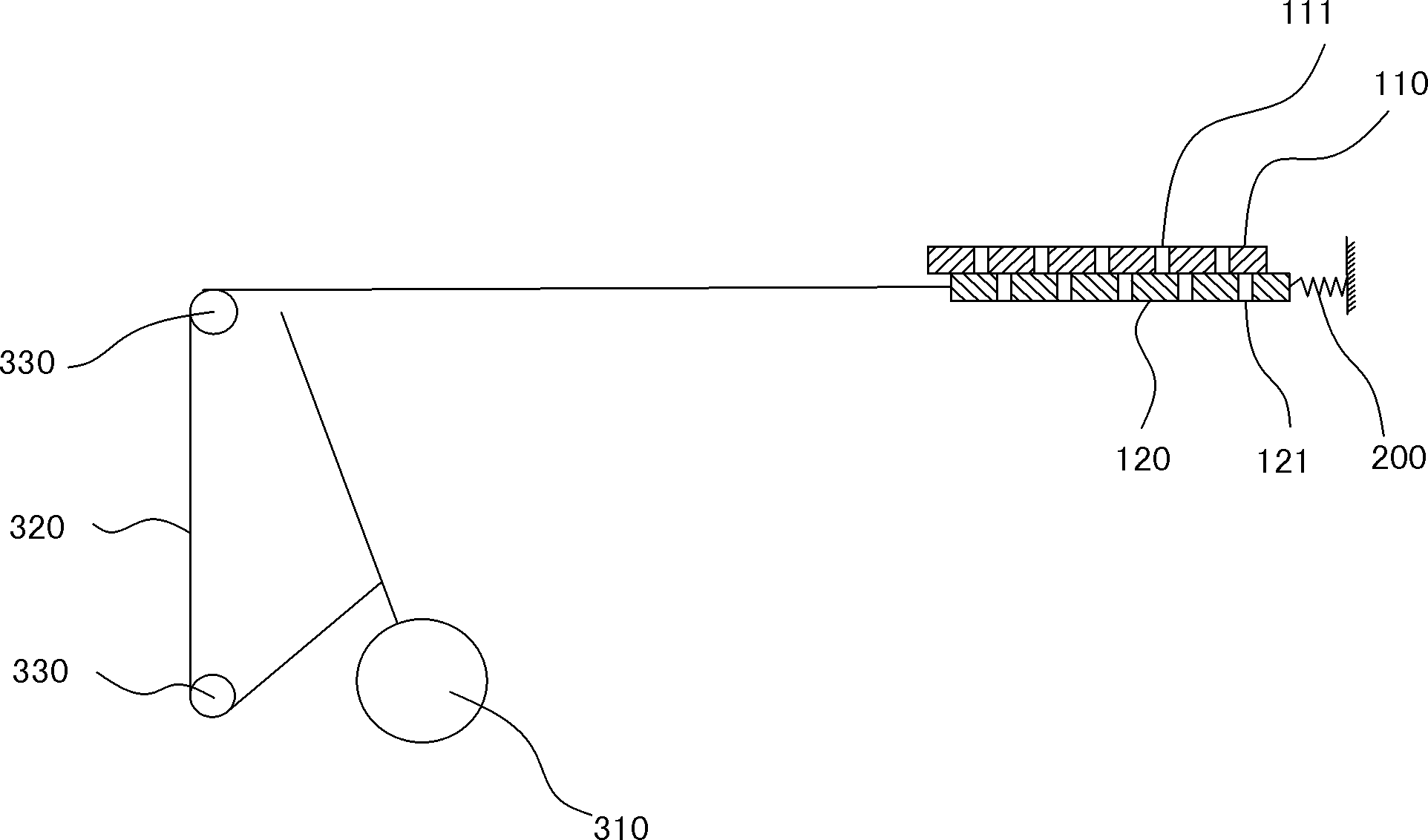
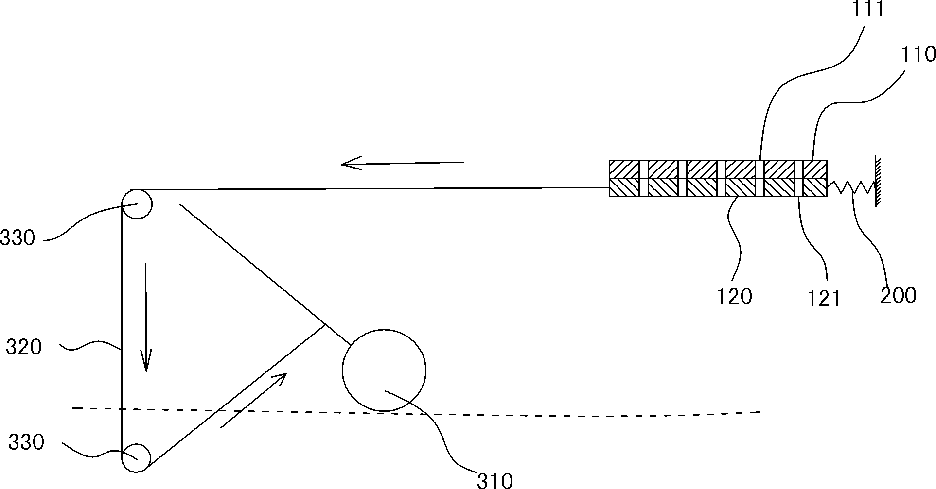
[0024] see figure 1 and 2 , a drainage structure applied to sewer pipes, comprising a baffle mechanism and a floating ball pulling mechanism for driving the baffle mechanism to open.

[0025] The baffle plate mechanism includes a fixed cover plate 110 and a movable cover plate 120, and a plurality of drain holes (111, 121) are arranged at intervals on the fixed cover plate and the movable cover plate, and the drain holes 111 on the fixed cover plate are connected with those on the movable cover plate. The drainage hole 121 is corresponding. The diameter of the drainage holes is 2cm-4cm, and the distance between adjacent drainage holes is 3cm-6cm. The fixed cover and the movable cover are stacked up and down, and the positions of the drain holes on the fixed cover and the drain holes on the movable cover are interlaced (such as figure 1 shown). One side of the movable cover is connected with the elastic return device 200 (a spring is used in this embodiment), and the other ...

Embodiment 2

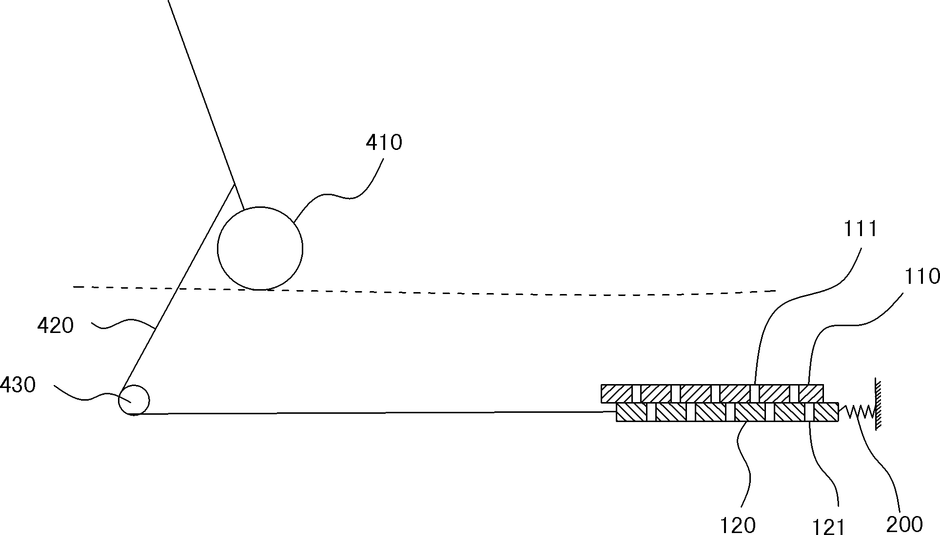
[0029] see image 3 and 4 , a drainage structure applied to rainwater pipes, comprising a baffle mechanism and a floating ball pulling mechanism that drives the baffle mechanism to open.

[0030] The baffle plate mechanism includes a fixed cover plate 110 and a movable cover plate 120, and a plurality of drain holes (111, 121) are arranged at intervals on the fixed cover plate and the movable cover plate, and the drain holes 111 on the fixed cover plate are connected with those on the movable cover plate. The drainage hole 121 is corresponding. The diameter of the drainage holes is 2cm-4cm, and the distance between adjacent drainage holes is 3cm-6cm. The fixed cover plate and the movable cover plate are stacked together up and down, and the positions of the drain holes on the fixed cover plate and the drain holes on the movable cover plate are interlaced. One side of the movable cover is connected with the elastic return device 200 (a spring is used in this embodiment), and...


PUM


Abstract

A pipeline drainage structure comprises a baffle mechanism and a floating ball pulling mechanism, wherein the baffle mechanism consists of a fixed cover plate and a movable cover plate which are vertically overlapped together and provided with drain holes, and the drain holes on the fixed cover plate and the drain holes on the movable cover plate are staggered in position; one side of the movable cover plate is connected with a spring, and the other side of the movable cover plate is connected with the floating ball pulling mechanism; and the floating ball pulling mechanism consists of a floating ball, a traction rope and a fixed pulley, one end of the traction rope is connected with the floating ball, and the other end of the traction rope is connected with the movable cover plate by bypassing the fixed pulley. The pipeline drainage structure utilizes the buoyancy principle; the floating ball falls naturally in low water level under the gravity action, and the movable cover plate of the baffle mechanism is reset under the pulling action of the spring, and at the moment, the baffle mechanism is closed; and when the water level rises, the floating ball rises under the action of buoyancy to drive the movable cover plate to move, so that the drain holes on the fixed cover plate and the drain holes on the movable cover plate are gradually coincident together, and the baffle mechanism is opened.

Description

technical field [0001] The invention relates to the construction field, in particular to a pipeline drainage structure. Background technique [0002] In our life, we often find that the sewer pipes and rainwater pipes are easily blocked due to various debris. For this reason, sanitation workers need to dredge and clean them again and again. In thunderstorms, the water pipes are often difficult to keep up with the drainage demand due to the runoff. On the one hand, the caliber of the sewer cover itself is too small to meet the needs of the abnormal flow rate; on the other hand, it is also the main aspect, because the sewer pipe is usually blocked by sundries to cause its runoff flow. As a result, the sanitation workers had to open the inspection wells one by one to make the accumulated water on the road flow down. The downpipe and rainwater pipe of this structure have many inconveniences to use. Contents of the invention [0003] The object of the present invention is to ...

Claims


Application Information

Patent Timeline
IPC IPC(8): E02D29/14
Inventor 叶铖
Owner SHANGHAI DATONG HIGH SCHOOL
Why Eureka
Try Eureka