Rotating shaft structure of displays

A shaft structure and display technology, applied to instruments, supporting machines, identification devices, etc., can solve problems such as difficult manufacturing and assembly, high unit price, and numerous components, and achieve great practical value, low cost, and easy manufacturing and assembly.

Inactive Publication Date: 2012-10-17
TOP VICTORY INVESTMENTS
View PDF6 Cites 1 Cited by
  • Summary
  • Abstract
  • Description
  • Claims
  • Application Information

AI Technical Summary

Problems solved by technology

[0006] The main purpose of the present invention is to solve the problem that the traditional flat panel display has many rotating shaft structural components, complex structure, difficult manufacture and assembly, and expensive unit price

Method used


Image

  • Rotating shaft structure of displays
  • Rotating shaft structure of displays
  • Rotating shaft structure of displays

Examples


Embodiment Construction

[0028] In order to make the object, technical solution and advantages of the present invention clearer, the implementation manner of the present invention will be further described in detail below in conjunction with the accompanying drawings.

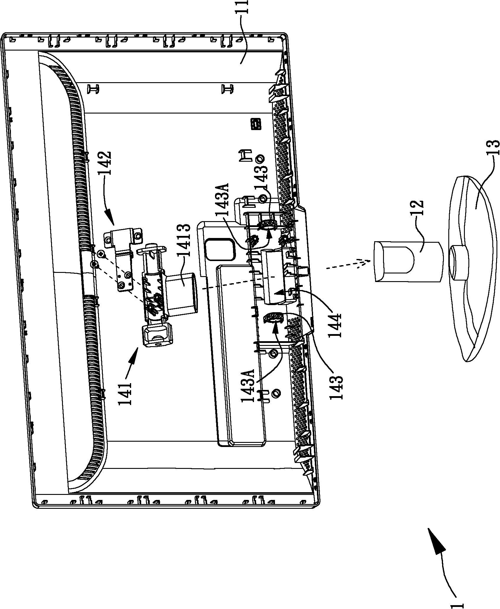
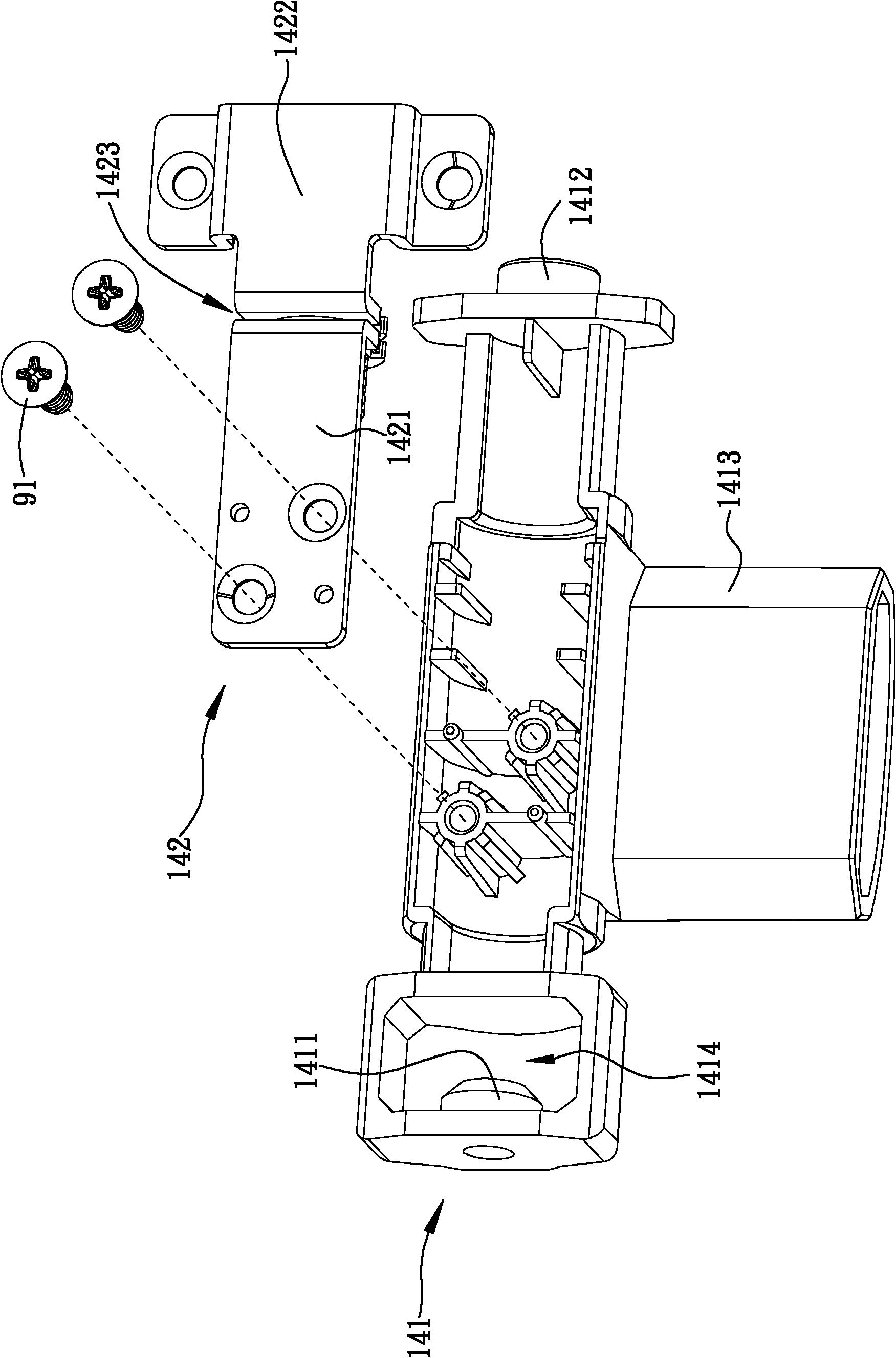
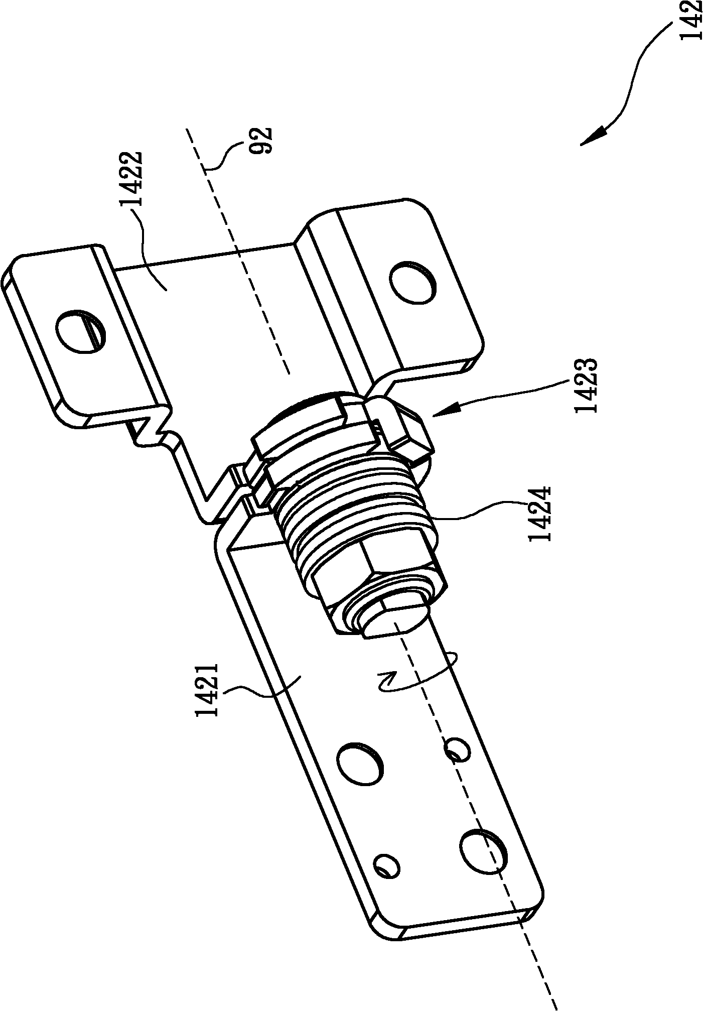
[0029] Please also see Figure 1A ~ Figure 1C , Figure 1A Shown is an exploded schematic view of the display shaft structure provided by the embodiment of the present invention, Figure 1B Shown is a schematic diagram of the combination of the first rotating shaft and the second rotating shaft of the display rotating shaft structure provided by the embodiment of the present invention, Figure 1C Shown is a schematic diagram of the second rotating shaft of the display rotating shaft structure provided by the embodiment of the present invention. like Figure 1A As shown, a display shaft structure is arranged on the display 1 , and the display 1 includes a rear case 11 , a bracket 12 and a base 13 . The display shaft structure includes...


PUM


Abstract

The invention provides a rotating shaft structure of displays. The rotating shaft structure of displays is arranged on a display, and the display comprises a rear shell and a base; the rotating shaft structure of displays comprises two bushes, a first rotating shaft and a second rotating shaft, wherein the two bushes are arranged on the inner side of the rear shell; the first rotating shaft comprises a first support part and a second support part, and the first support part and the second support part are respectively arranged in the two bushes, so that the first shaft rotates by taking the central axis of the two bushes as an axis center; and the second rotating shaft comprises a first fixed part, a second fixed part and a pin-jointed part, the first fixed part and the second fixed part can rotate relative to each other, the first fixed part and the first rotating shaft are combined and fixed, and the second fixed part and the rear shell are combined and fixed, therefore, the rear shell can be supported and fixed on the base through the rotating shaft structure for displays. The rotating shaft structure for displays disclosed by the invention is simple in structure and low in cost, and has great practical values.

Description

technical field [0001] The invention relates to a rotating shaft structure, in particular to a display rotating shaft structure used in a display. Background technique [0002] In recent years, since the manufacturing cost of the flat-panel display has been significantly reduced, the flat-panel display has gradually become the mainstream of home TV and computer screens. In addition, because flat-panel displays are lighter and thinner than traditional TVs using cathode ray tubes, more and more flat-panel displays can be found in public places such as train stations, hospitals, convenience stores or movie theaters. For the display of information, it can also be used for advertising, and its commercial application can be said to be more and more extensive. [0003] Generally speaking, a flat-panel display contains many parts inside, including a liquid crystal panel, a backlight module, a circuit board, a heat dissipation structure, a front case and a rear case, etc. The flat-p...

Claims


Application Information

Patent Timeline
Patent Type & Authority Applications(China)
IPC IPC(8): F16M11/10G09F9/30
Inventor 留志宏
Owner TOP VICTORY INVESTMENTS
Why Eureka
Try Eureka