Refrigeration thermal infrared imager and power supply management method thereof

An infrared thermal imager and power management technology, which is applied in the field of infrared thermal imaging, can solve the problems that cooling infrared thermal imagers cannot realize hot plugging and hot switching, prolong the working time and life of the battery, etc., so as to prolong the working time and life , the effect of protecting the battery

Active Publication Date: 2012-10-17
NO 717 INST CHINA MARINE HEAVY IND GRP
View PDF5 Cites 10 Cited by
  • Summary
  • Abstract
  • Description
  • Claims
  • Application Information

AI Technical Summary

Problems solved by technology

[0004] The purpose of the present invention is: to overcome the shortcomings of the prior art, solve the problem that the cooling infrared camera in the prior art cannot realize hot plugging and hot switching, no need to shut down when the battery is exhausted, and ensure uninterrupted reconnaissance of the target and monitoring; it can monitor the battery power and external power supply voltage in real time, and the circuit board will have no standby current after fully shutting down, prolonging the working time and life of the battery; power output overcurrent and overvoltage, short circuit protection and battery mutual charging and reverse charging protection; using isolated output, Thereby reducing mutual interference and ineffective power consumption

Method used


Image

  • Refrigeration thermal infrared imager and power supply management method thereof
  • Refrigeration thermal infrared imager and power supply management method thereof
  • Refrigeration thermal infrared imager and power supply management method thereof

Examples


Embodiment 1

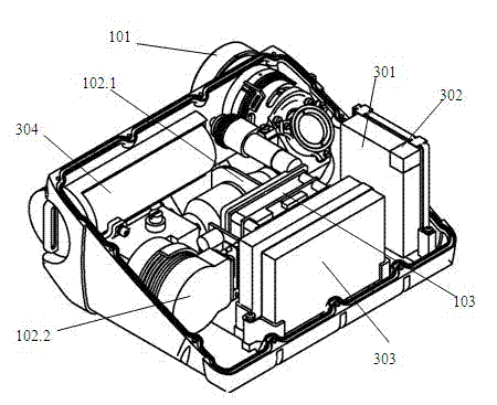
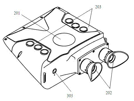
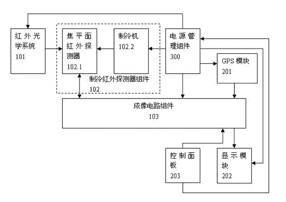
[0059] It is a basic embodiment of a cooled infrared camera. A cooling infrared thermal imager, which includes an infrared optical system 101, a cooling infrared detector assembly 102, an imaging circuit assembly 103, a power management assembly 300, a GPS module 201, a display module 202, and a control panel 203; the infrared optical system After 101, a cooling infrared detector assembly 102 including a focal plane infrared detector 102.1 and a refrigerator 102.2 is connected; the focal plane infrared detector 102.1 is connected to the imaging circuit assembly 103 in addition to being connected to the infrared optical system 101 and the refrigerator 102.2 respectively ; The imaging circuit assembly 103 is also connected with the GPS module 201, the display module 202, and the control panel 203 respectively; 202 and control panel 203 are connected.

[0060] Such as image 3 As shown, the working principle and steps of the cooling infrared thermal imager are explained as foll...

Embodiment 2

[0071] It is a further example on the basis of Example 1. Such as image 3 As shown, the power management assembly 300 includes a power management circuit 301, a charging circuit 302, an internal battery 303, an external battery 304 and an external power supply interface 305; the external power supply interface 305 is connected to the power management circuit 301; charging The input end of the circuit 302 is connected to the external power supply, and the output end is connected to the internal battery 303, the external battery 304 and the power management circuit 301 respectively; the input end of the external battery 304 is connected to the charging circuit 302, and the output end is connected to the power management circuit 301; the internal battery The input terminal of 303 is connected with the charging circuit 302, and the output terminal is connected with the power management circuit 301; the input terminal of the power management circuit 301 is not only connected with ...

Embodiment 3

[0074] It is an embodiment of the power supply method applied to the cooling infrared thermal imager of the present invention when there is external power supply: the cooling infrared thermal imaging camera of the method includes an infrared optical system 101, a cooling infrared detector assembly 102, and an imaging circuit assembly 103 , power management component 300, GPS module 201 and display module 202 and control panel 203; The power supply method of described cooling infrared thermal imager when having external power supply comprises the following steps:

[0075] a1. The external power supply enters the power management circuit 301 through the external power supply interface 305, and after passing through the D6 diode 301.23, the current detection and voltage detection module 301.2 and the voltage conversion module 301.3 in the power management circuit 301, it is converted into the voltage value specified by other components , for powering on each component except the r...


PUM


Abstract

The invention relates to a refrigeration thermal infrared imager and a power supply management method of the refrigeration thermal infrared imager. The refrigeration thermal infrared imager comprises an infrared optical system, a refrigeration infrared prober assembly, an imaging circuit assembly, a power supply management assembly, a GPS (global position system) module, a display module and a control panel; the refrigeration infrared prober assembly consisting of a focal plane infrared prober and a refrigerator is connected behind the infrared optical system; the imaging circuit assembly is further respectively connected with the GPS module, the display module and the control panel; and the power supply management assembly is respectively connected with the infrared optical system, the refrigerator, the imaging circuit assembly, the GPS module, the display module and the control panel. The refrigeration thermal infrared imager provided by the invention has the advantages as follows: hot switching and hot plugging of power supply can be realized, so that a target can be continuously detected and monitored; electric amount of a battery and external power supply voltage can be monitored in real time; a circuit board has no standby current after the refrigeration thermal infrared imager is switched off, so that the working time and the service life of the battery can be prolonged; the over-current, overvoltage, short circuit protection in power supply output, and manual charge and inverse charge protection of the battery can be realized; and the refrigeration thermal infrared imager uses isolation output, so that mutual interference and invalid power consumption can be reduced.

Description

technical field [0001] The invention relates to a refrigerated infrared thermal imager and a power management method thereof, in particular to a miniaturized refrigerated infrared thermal imager supporting hot plugging, and belongs to the technical field of infrared thermal imaging. Among them, the power management method involves: the power supply method with and without external power supply, the hot swap method of external power supply with external power supply, the hot swap method of external battery and the switching method of external battery. Background technique [0002] Information collection is an important part of information warfare, which determines the direction of the confrontation situation. Due to the advantages of good flexibility and concealment of thermal imaging cameras, single-person reconnaissance has gradually become an important means of field information collection. Among the single-person reconnaissance equipment, the thermal imaging camera has t...

Claims


Application Information

Patent Timeline
IPC IPC(8): G01J5/10H02J7/36H02J9/04
Inventor 潘德彬张智杰洪普王晨晟郭晓东
Owner NO 717 INST CHINA MARINE HEAVY IND GRP
Why Eureka
Try Eureka