
Method for eliminating interference during signal sampling

A technology for eliminating signals and sampling values, applied in measurement devices, instruments, measuring electrical variables, etc., can solve problems such as large system resource consumption, the possibility of obtaining real values, and the sampling signal not being able to truly reflect the state of the monitored signal.

Active Publication Date: 2012-10-17
SHANDONG SINOCHIP SEMICON
View PDF5 Cites 4 Cited by
  • Summary
  • Abstract
  • Description
  • Claims
  • Application Information

AI Technical Summary

Problems solved by technology

Since the sampling process will inevitably be restricted by the surrounding environment, resulting in interference, the output sampling signal cannot truly reflect the state of the monitored signal
Therefore, in further applications, the sampling signal is processed by means of filtering, etc. However, it is still impossible to remove the false value according to this method
The reason is that filtering can only eliminate relatively small interference. If a glitch is generated due to interference at a certain moment, and the glitch is just sampled at the sampling time, it is easy to misjudge the interference value as the real value.
[0005] Obviously, the existing sampling methods basically obtain the sampling signal that truly reflects the monitored signal by processing the signal obtained after sampling. Due to the characteristics of the sampling signal itself, even if the subsequent processing circuit is good enough, it may not be able to Obtaining the real value, the elimination of signal sampling interference encountered a technical bottleneck
At the same time, more and more complex follow-up processing circuits will inevitably increase relatively large costs, and the system resource consumption will also be relatively large

Method used


Image

  • Method for eliminating interference during signal sampling
  • Method for eliminating interference during signal sampling

Examples


Embodiment Construction

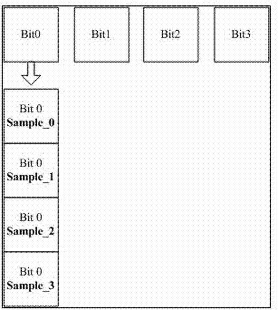
[0015] Refer to the attached figure 1 , the sampled signal Bit0~Bit3, that is, 4 groups of signals are sampled in one sampling period, the sampling register Sample0~3, a group of 4.

[0016] Description of the sampling process:

[0017] 1. Use four consecutive clock cycles, that is, use four consecutive working cycles to complete four samplings of Bit0, and write to Sample0 to Sample3 in sequence.

[0018] 2. Compare the values ​​stored in the four registers Sample0, Sample1, Sample2, and Sample3. If they are the same, determine the value as the sampling value of Bit0. If they are different, the sampling value is invalid and discarded.

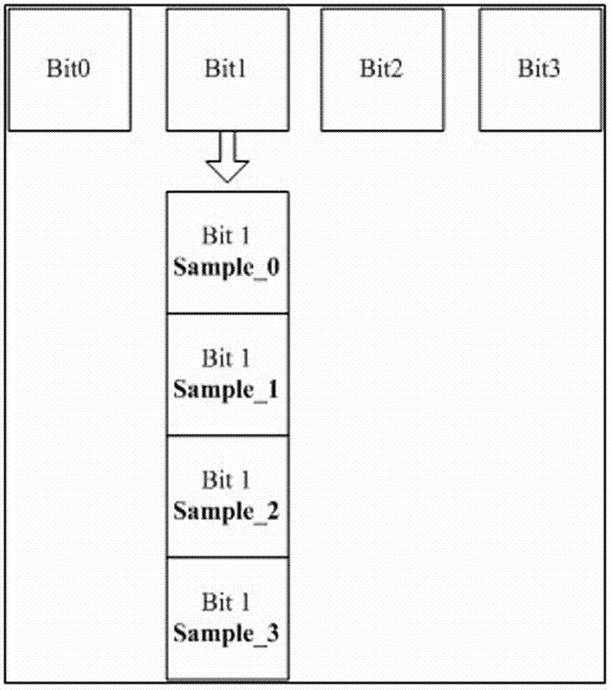
[0019] 3. Sample Bit1 in the next four clocks, and write to Sample0, Sample1, Sample2, and Sample3 in sequence.

[0020] 4. Compare the values ​​stored in the four registers Sample0, Sample1, Sample2, and Sample3. If they are the same, determine the value as the sampling value of Bit1. If they are different, the sampling value is invalid and...


PUM


Abstract

The invention discloses a method for eliminating interference during signal sampling. The method is applied to a sampling system of which a ratio of the working frequency to the sampling frequency is n and comprises the following steps of: sampling once in each of m continuous working periods in a sampling period; sequentially storing obtained sampling values into a distributed sampling register group; taking the sampling values out of the sampling register group, comparing the sampling values and outputting the sampling values which are large in amount in the m sampling times as an output values of the current sampling period, wherein 2 is less than m, and m is less than n. According to the method, the interference during signal sampling can be effectively eliminated, so that the system expense can be reduced; and furthermore, the probability of acquiring a real value is relatively high, so that the improvement room is relatively large.

Description

technical field [0001] The invention relates to a method for eliminating interference in signal sampling. Background technique [0002] Sampling is also called sampling, which is the discretization of the signal in time, that is, the instantaneous value is taken point by point on the analog signal x(t) according to a certain time interval △t. It is realized by multiplying the sampling pulse and the analog signal. [0003] Selection of sampling interval and signal confusion: To sample an analog signal, the sampling interval must first be determined. How to choose △t reasonably involves many technical factors that need to be considered. Generally speaking, the higher the sampling frequency, the denser the number of sampling points, and the closer the obtained discrete signal is to the original signal. However, an excessively high sampling frequency is not advisable. For a fixed length (T) signal, an excessively large amount of data (N=T / △t) is collected, which adds unnecess...

Claims


Application Information

Patent Timeline
IPC IPC(8): G01R29/00
Inventor 刘大铕陆崇心张洪柳孙晓宁
Owner SHANDONG SINOCHIP SEMICON
Learn More