End cover assembly of battery

A technology for end caps and batteries, which is applied to battery pack components, small-sized batteries/battery packs, battery boxes/coats, etc., and can solve problems such as inability to maintain airtightness and electrolyte leakage

Active Publication Date: 2015-02-04
IND TECH RES INST
View PDF6 Cites 0 Cited by
  • Summary
  • Abstract
  • Description
  • Claims
  • Application Information

AI Technical Summary

Problems solved by technology

[0005] The purpose of the present invention is to provide a battery end cover group, which can solve the problems caused by the leakage of the existing electrolyte and other problems caused by the inability to maintain airtightness

Method used


Image

  • End cover assembly of battery
  • End cover assembly of battery
  • End cover assembly of battery

Examples


Embodiment Construction

[0047] Hereinafter, reference is made to the drawings in order to more fully describe embodiments of the present invention. However, the invention may be practiced in many different forms and should not be construed as limited to the embodiments set forth herein. In addition, the sizes and relative sizes of layers and regions may be exaggerated in the drawings for the sake of clarity and not drawn to scale.

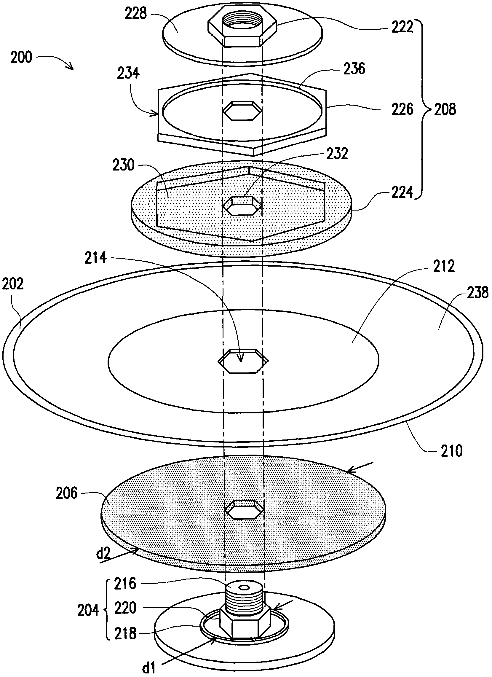
[0048] figure 2 It is a three-dimensional exploded view of a battery end cover assembly of an embodiment.

[0049] Please refer to figure 2 , the battery end cover assembly 200 includes a battery end cover 202 , a terminal base 204 , an airtight insulating gasket 206 and a fixing component 208 . The battery end cover 202 has a first surface 210 and a second surface 212 opposite to each other and a first opening 214 passing through the first and second surfaces 210 , 212 . The terminal base 204 is located on the first surface 210 of the battery end cover 202. The ter...


PUM


Abstract

An end cover assembly of battery includes a battery end cover, a terminal substrate, an airtight insulating pad and a secure assembly. The battery end cover has first and second surfaces and a first opening. The terminal substrate is disposed on the first surface of the battery end cover and has a protrusion portion and a airtight ring, wherein the protrusion portion penetrate through the battery end cover through the first opening, and the airtight ring is disposed towards the battery end cover around the protrusion portion. The airtight insulating pad is sandwiched between the terminal substrate and the battery end cover. The secure assembly is disposed on the second surface of the battery end cover to collaborate with the terminal substrate for fixing the battery end cover and making the battery end cover and the airtight ring to press the airtight insulating pad to achieve an airtight effect.

Description

technical field [0001] The present invention relates to an end cover assembly of battery, and in particular to an end cover assembly capable of maintaining airtight effect for a long time. Background technique [0002] The end cap group of the traditional secondary battery such as figure 1 As shown, a terminal base 100, a battery end cap 102, a gasket 104 disposed between the terminal base 100 and the battery end cap 102, and a screw cap 106 are shown therein. In addition, the gasket 108 having an airtight or insulating function is isolated between the screw cap 106 and the battery end cover 102 . finally figure 1 The battery end cap group will be welded with the tank body of the secondary battery. However, when the above-mentioned structure is locked to the terminal base 100 by the external power cord, it is easy to cause air leakage between the base 110 of the terminal base 100 and the battery end cover 102 due to rotation due to too much force, causing electrolyte leak...

Claims


Application Information

Patent Timeline
Patent Type & Authority Patents(China)
IPC IPC(8): H01M2/04H01M50/172
CPCH01M2/30H01M2/0478H01M2/046H01M2/06Y02E60/10H01M50/152H01M50/172
Inventor 叶胜发
Owner IND TECH RES INST
Why Eureka
Try Eureka