Rotary inflating nozzle

An inflatable nozzle and rotary technology, which is applied in the direction of variable volume pump components, liquid variable volume machinery, machines/engines, etc. The effect of reducing overall structural length and material usage

Inactive Publication Date: 2012-02-01
黄英哲 +1
View PDF7 Cites 0 Cited by
  • Summary
  • Abstract
  • Description
  • Claims
  • Application Information

AI Technical Summary

Problems solved by technology

[0004] However, the known structure must still have the design of the chamber 51 on the overall characteristics, mainly to make the valve plug 25 and the core tube 24 be limited in its internal space, so the depth of the chamber 51 still has a design. A certain volume is occupied, and the consumption of metal materials is virtually increased. The main reason is that if th

Method used


Image

  • Rotary inflating nozzle
  • Rotary inflating nozzle
  • Rotary inflating nozzle

Examples


Embodiment Construction

[0046] In order to have a clearer understanding of the technical features, purposes and effects of the present invention, the specific implementation manners of the present invention will now be described with reference to the accompanying drawings, wherein the same components use the same reference numerals.

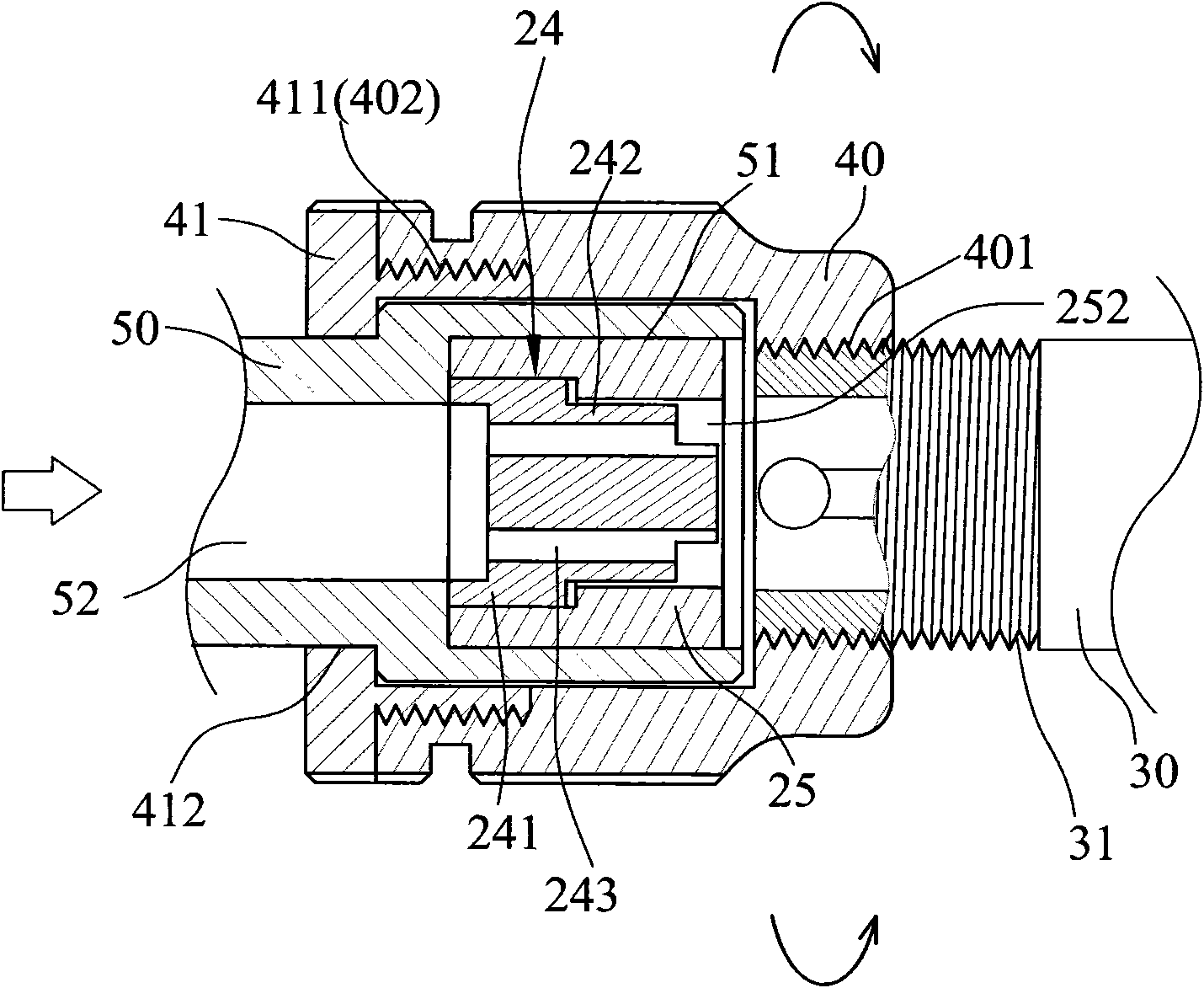
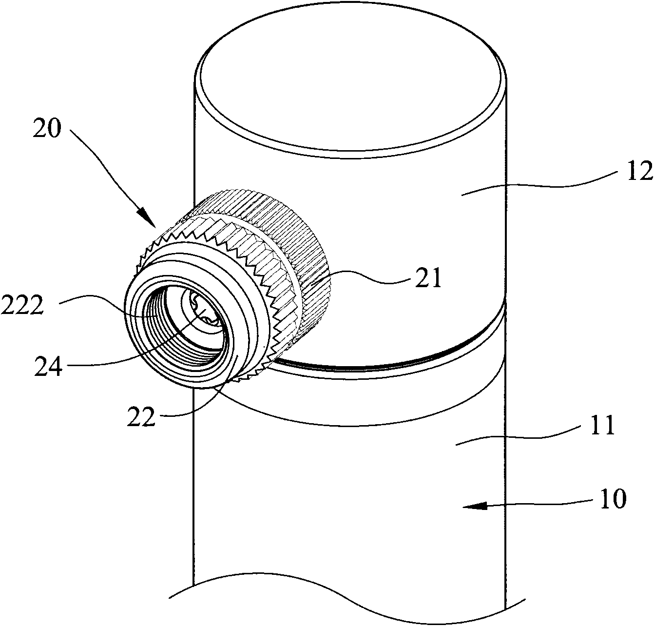
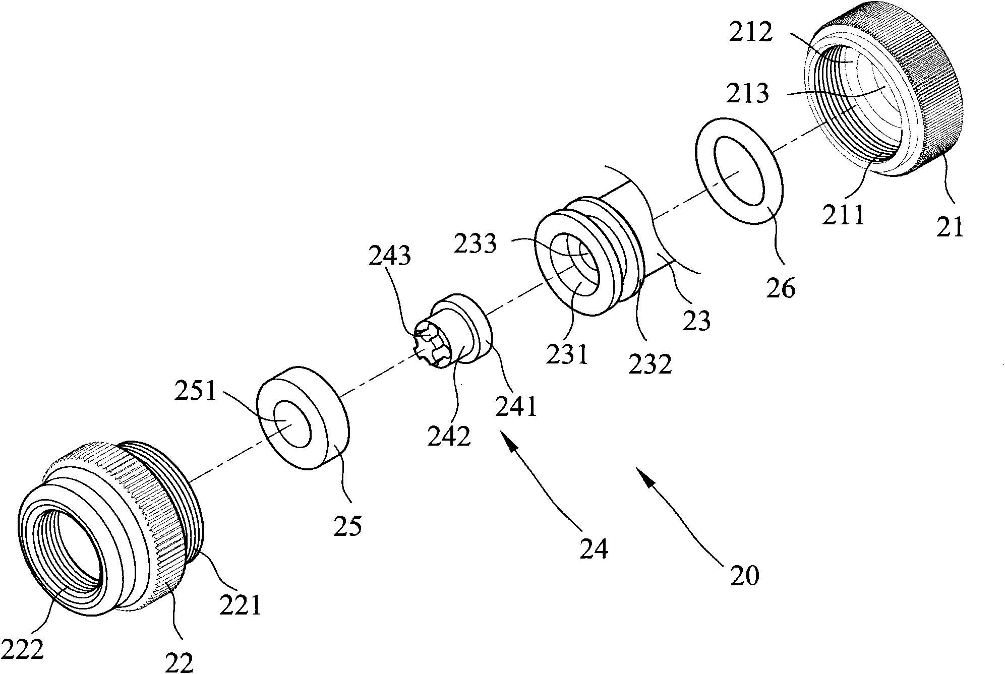
[0047] see figure 2 , image 3 and Figure 4 The schematic diagram of structural assembly and disassembly of the preferred embodiment of the present invention is shown, and the structural design of the rotary air filling nozzle 20 of the present invention can improve the length occupied by the chamber at the front end of the air nozzle plug group seat in the known structure and the volume, so the present invention cancels such as figure 1The design of the chamber 51 in the prior art shown is to keep the positioning effect of the valve plug 25 and the core tube 24, and to avoid the rotation of the valve plug 25 due to the housing 22 after the design of the chamber 51 ...


PUM


Abstract

The invention provides a rotary inflating nozzle, which is provided with an air nozzle plug group seat, wherein a case and a cap cover are covered on the periphery of the air nozzle plug group seat, a center propping pipe and an air nozzle plug are sheathed in the center of the front end of the air nozzle plug group seat, the air nozzle plug group seat is provided with a sheathing part, and a limiting end with large circle diameter is formed at the front end of the air nozzle plug group seat, wherein the center propping pipe is provided with a first embedding end and a second embedding end, the first embedding end is positioned through being sheathed in the sheathing part, the center hole of the air nozzle plug is positioned through being sheathed on the second embedding end of the center propping pipe, and the goals of reducing the size consumption, reducing the integral structural length and reducing the material consumption are reached.

Description

technical field [0001] The invention relates to a rotary inflation nozzle, in particular to a rotary inflation nozzle for providing an air pump. Background technique [0002] see figure 1 The known rotary aeration nozzle structure side sectional schematic diagram shown, this known rotary aeration nozzle is the implementation structure design of the inventor's previously applied for invention patent approval (Chinese Taiwan invention patent No. I307388 / U.S. invention patent No. US 7,588,048 B2), the invention patent discloses that there is an outer shell 40 on the valve plug set seat 50 connected to the air outlet end of the pump (not shown in the figure), wherein the shell 40 is inside one end of the valve plug set seat 50 There is a chamber 51 at the position, the rear end of the chamber 51 extends with an air delivery hole 52, the air delivery hole 52 is connected backwards and leads to the outlet of the aforementioned air pump, so as to guide the air from the inside for ...

Claims


Application Information

Patent Timeline
IPC IPC(8): F04B39/12
Inventor 黄英哲黄俊铭
Owner 黄英哲
Why Eureka
Try Eureka