Supercharge Your Innovation With Domain-Expert AI Agents!

Lens antenna with function of converging electromagnetic waves

A lens antenna, electromagnetic lens technology, applied to antennas, electrical components, etc., can solve the problems of difficult implementation of actual processes, large variation range, large size, etc., and achieve the effect of reducing the overall volume, reducing requirements, and being convenient to use.

Active Publication Date: 2015-02-04
KUANG CHI INST OF ADVANCED TECH +1
View PDF2 Cites 0 Cited by
  • Summary
  • Abstract
  • Description
  • Claims
  • Application Information

AI Technical Summary

Problems solved by technology

However, the existing problems in the existing technology are: to make the electromagnetic waves converge, the dielectric constant needs to change continuously within the scale range of the metamaterial, and the continuous change makes the variation range of the dielectric constant very large, while the metamaterial When designing the artificial microstructure, it is difficult to make its size very large, so it is difficult to implement in the actual process, and it is a technical problem that needs to be solved urgently

Method used


Image

  • Lens antenna with function of converging electromagnetic waves
  • Lens antenna with function of converging electromagnetic waves
  • Lens antenna with function of converging electromagnetic waves

Examples


Embodiment 1

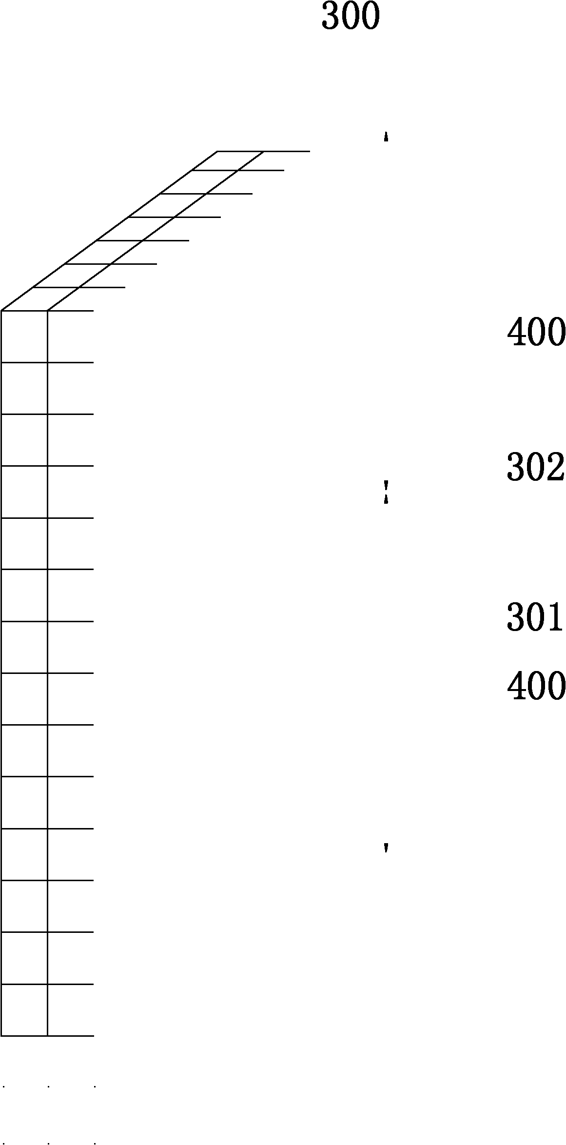
[0027] The electromagnetic lens 200 of this embodiment is formed by stacking multi-layer metamaterial functional boards 300 sequentially. For the structural diagram of the metamaterial functional board 300, please refer to the attached image 3 , the metamaterial functional board 300 is composed of a dielectric substrate 301 and a plurality of artificial microstructures 302 arrayed on the dielectric substrate. The artificial microstructures 302 and the dielectric substrate 301 they occupy form a metamaterial unit. The metamaterial unit has a specific Structural and electromagnetic properties, generally when the size of a single artificial microstructure 302 is less than 1 / 10 of a wavelength, it has an electrical or magnetic response to an external electric or magnetic field, thereby exhibiting an equivalent dielectric constant or equivalent magnetic permeability In this embodiment, by designing the shape of each artificial microstructure 302 as an I-shape, and making each I-sha...

Embodiment 2

[0031] The electromagnetic lens 200 of this embodiment is formed by stacking multi-layer metamaterial functional boards 300 sequentially. For the structural diagram of the metamaterial functional board 300, please refer to the attached Figure 5, the metamaterial functional board 300 is composed of a dielectric substrate 301 and a plurality of artificial microstructures 302 arrayed on the dielectric substrate. The artificial microstructures 302 and the dielectric substrate 301 they occupy form a metamaterial unit. The metamaterial unit has a specific Structural and electromagnetic properties, generally when the size of a single artificial microstructure 302 is less than 1 / 10 of a wavelength, it has an electrical or magnetic response to an external electric or magnetic field, thereby exhibiting an equivalent dielectric constant or equivalent magnetic permeability In this embodiment, by designing the shape of each artificial microstructure 302 as an I-shaped derivative, and makin...


PUM


Abstract

The invention provides a lens antenna with a function of converging electromagnetic waves. The lens antenna comprises a radiator and an electromagnetic lens. The electromagnetic lens is made of metamaterial, and the metamaterial is combined by a metamaterial functional plate array. The metamaterial functional plates include a central position, and one side of the central position includes a plurality of metamaterial zones with refractive indexes of the zones in a zonal distribution. The refractive indexes in each metamaterial zone continuously change toward a same direction, the side with larger refractive indexes in each metamaterial zone is toward the central position, and the side with smaller refractive indexes in each metamaterial zone is toward the side of the metamaterial functional plate. The refractive indexes on a border position of the metamaterial zone change non-continuously. Beneficial effects of the lens antenna are that using the metamaterial to replace various shaped lens in the lens antenna and making the lens antenna with the metamaterial, requirements of lens processing technology can be reduced, precision of the lens is improved, a whole volume of the lens antenna is reduced, and using the lens antenna is more convenient.

Description

【Technical field】 [0001] The invention relates to an electromagnetic lens antenna, in particular to a lens antenna with electromagnetic wave converging function. 【Background technique】 [0002] In conventional optical devices, the lens can make the spherical wave radiated by the point light source placed on the focal point of the lens become a plane wave after being refracted by the lens. Lens antennas are made using this principle. It consists of a lens and a radiator placed at the focal point of the lens. [0003] The lens antenna is an antenna that uses the characteristics of lens convergence to transmit the electromagnetic wave radiated by the radiator through the lens, and the energy is concentrated and then emitted. This antenna has strong directivity. [0004] The convergence of the lens is realized by the refraction of the spherical shape of the lens. The process of manufacturing the lens is complicated and the precision is not high. Therefore, the lens antenna ha...

Claims


Application Information

Patent Timeline
Patent Type & Authority Patents(China)
IPC IPC(8): H01Q19/06H01Q15/02
Inventor 刘若鹏季春霖岳玉涛王今金
Owner KUANG CHI INST OF ADVANCED TECH
Features
  • R&D
  • Intellectual Property
  • Life Sciences
  • Materials
  • Tech Scout
  • Unparalleled Data Quality
  • Higher Quality Content
  • 60% Fewer Hallucinations
Learn More