Compact photon structure capable of realizing various resonance line types based on micro ring cavity

A photonic structure and micro-ring technology, which is applied in the coupling of optical waveguides, etc., can solve the problem of insufficient compactness, and achieve the effect of small processing error, low processing technology requirements, and compact photonic structure

Inactive Publication Date: 2017-07-25
NORTHWESTERN POLYTECHNICAL UNIV
View PDF4 Cites 7 Cited by
  • Summary
  • Abstract
  • Description
  • Claims
  • Application Information

AI Technical Summary

Problems solved by technology

The Mach-Zehnder interference structure adds a straight waveguide on the basis of the waveguide-micro-ring cavity coupling structure, and needs to keep a certain distance from the original waveguide, so it is not compact enough
The Bragg grating reflective structure is a grating structure carved on a straight waveguide or a micro-ring cavity. Although it meets the compactness requirements, it has high requirements for processing technology and is only for a single wavelength.
[0005] In addition, by cascading multiple microring cavities, a transparent window similar to the phenomenon of electromagnetically induced transparency can be generated on the transmission spectrum of the waveguide-microring cavity coupling structure, that is, the transmission spectrum shows a peak rather than a depression at the resonance wavelength. , can be used for special purposes such as optical delay lines, but it also has the problem of not being compact enough, and it is a huge challenge to accurately control the resonance wavelength of multiple microring cavities at the same time

Method used


Image

  • Compact photon structure capable of realizing various resonance line types based on micro ring cavity
  • Compact photon structure capable of realizing various resonance line types based on micro ring cavity
  • Compact photon structure capable of realizing various resonance line types based on micro ring cavity

Examples


Embodiment Construction

[0029] Now in conjunction with embodiment, accompanying drawing, the present invention will be further described:

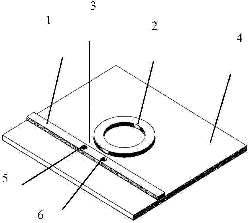
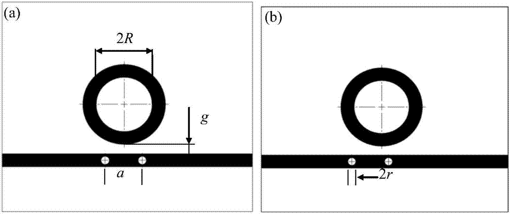
[0030] The embodiment of the present invention proposes a compact photonic structure based on a microring cavity to realize multiple resonance line types, such as figure 1 As shown in Fig. 1, the structure is based on the traditional micro-ring cavity side-coupled straight waveguide structure, and two air holes are dug out in the straight waveguide. Two air holes can be distributed symmetrically about the microring cavity figure 2 (a), also available off-centre figure 2 (b).

[0031] The materials used for the straight waveguide 1 and the micro-ring cavity 2 are generally high refractive index or have a high refractive index relative to its substrate and cladding, and there are group IV materials such as silicon, silicon nitride, silicon oxynitride, etc., III-V semiconductor materials such as gallium phosphide, lithium niobate, and certain polymers such as p...


PUM


Abstract

The invention relates to a compact photon structure capable of realizing various resonance line types based on a micro ring cavity. The compact photon structure comprises a straight waveguide (1), a micro ring cavity (2) and a substrate (4), and is characterized in that the straight waveguide (1) and a micro ring cavity (2) are located on the substrate (4), and a gap is reserved between the straight waveguide (1) and the micro ring cavity (2); the straight waveguide (1) is provided with two air holes; and the straight waveguide (1) and the micro ring cavity (2) are equal in thickness d and width w, and the straight waveguide (1) and the micro ring cavity mutually adopt lateral coupling. The beneficial effects comprise that the photon structure is compact, not only can realize various resonance line types at a specific resonant wavelength of a transmission spectrum of a waveguide-micro ring cavity coupling structure, but also has the characteristic at multiple resonant wavelengths in a wide band range, and can meet the demand of realizing various applications by using the single micro ring cavity.

Description

technical field [0001] The invention belongs to the field of optoelectronic integrated chips, and in particular relates to a compact photonic structure capable of realizing multiple resonance line shapes based on a micro-ring cavity on a photonic chip. Background technique [0002] A microring cavity is a typical optical cavity. With very compact structure size, high quality factor and extinction ratio, it is one of the important photonic devices constituting optoelectronic integrated chips. Through integration with other active or passive devices, microring cavities have been widely used in on-chip optical interconnects, optical sensor chips and other fields. [0003] On the photonic chip, the function of the micro-ring cavity generally needs to be coupled with a channel waveguide side, that is, a waveguide-micro-ring cavity coupling structure is formed, so that the resonant optical field signal in the micro-ring cavity can be measured. After the light is coupled into the...

Claims


Application Information

Patent Timeline
Patent Type & Authority Applications(China)
IPC IPC(8): G02B6/26
CPCG02B6/26
Inventor 甘雪涛顾林棚赵建林赵晨阳郑建邦
Owner NORTHWESTERN POLYTECHNICAL UNIV
Why Eureka
Try Eureka