Electric brake booster

An electric braking and booster technology, applied in the field of vehicles, can solve the problems of low transmission efficiency, low working noise, complex processing and installation, weak deceleration ability, etc., and achieve the effects of solving complex processing and installation, low installation cost and simple installation.

Active Publication Date: 2017-05-31
SAIC GENERAL MOTORS +1
View PDF5 Cites 7 Cited by
  • Summary
  • Abstract
  • Description
  • Claims
  • Application Information

AI Technical Summary

Problems solved by technology

[0004] Based on the above problems, the present invention proposes an electric brake booster, which solves the weak deceleration ability caused by the structure of the electric brake booster based on the rack and pinion in the prior art, and the friction caused by the sliding friction between the gear and the rack. The resulting low transmission efficiency and working noise; at the same time, it also solves the problems of complex processing and installation, high cost and difficult promotion caused by the structure of the electric brake booster based on the ball screw mechanism

Method used


Image

  • Electric brake booster
  • Electric brake booster
  • Electric brake booster

Examples


Embodiment Construction

[0040] The present invention will be further described in detail below in conjunction with specific embodiments and accompanying drawings. It is only intended to describe the specific implementation of the present invention in detail, and does not impose any limitation on the present invention, and the scope of protection of the present invention shall be determined by the claims.

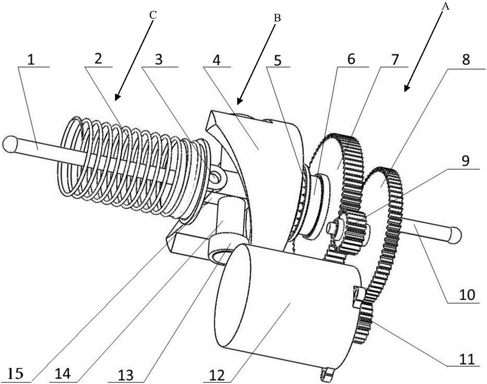
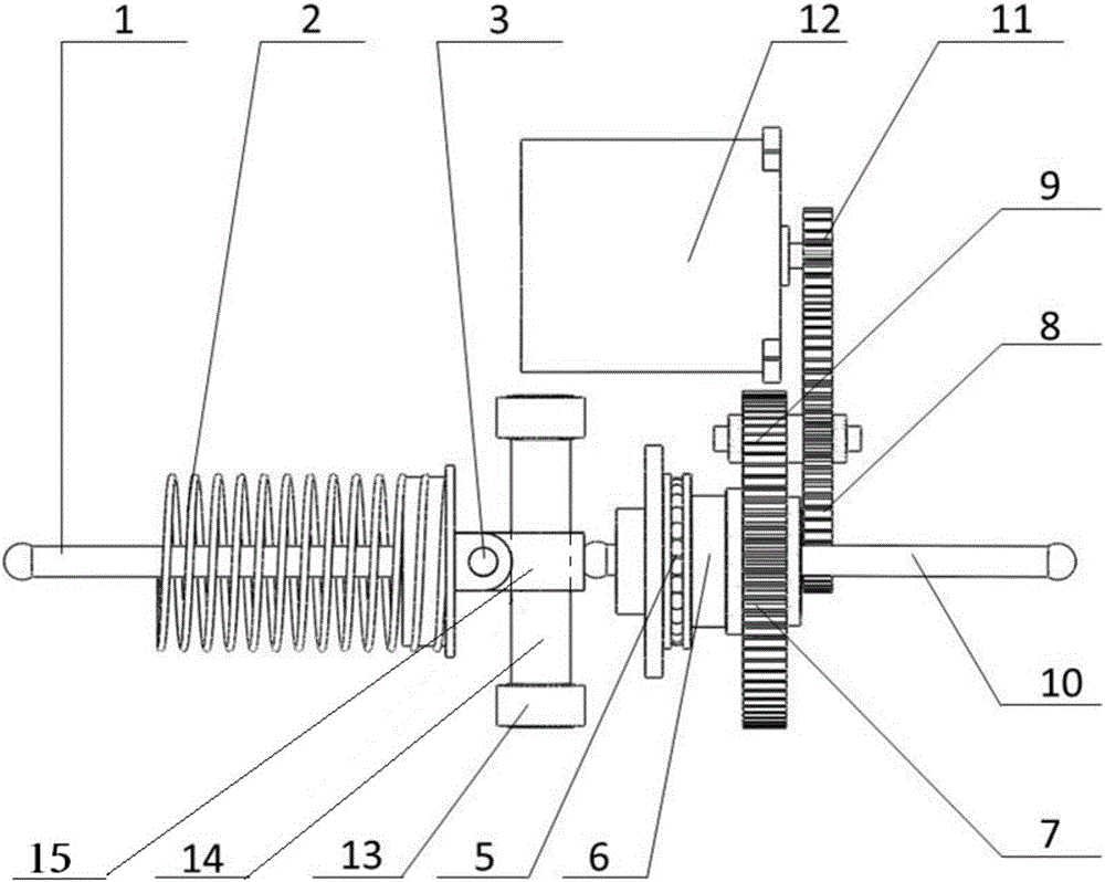
[0041] refer to figure 1 , the present invention proposes an electric brake booster, comprising:

[0042] Pedal push rod 10, motor 12, reduction mechanism A, cam mechanism B and booster C;

[0043] The first end of the pedal push rod 10 is connected to the brake pedal, the second end of the pedal push rod 10 is connected to the first end of the reduction mechanism A, the second end of the reduction mechanism A is connected to the first end of the cam mechanism B, and the cam The second end of the mechanism B is connected to the booster C, and the motor 12 is connected to the third end of the redu...


PUM


Abstract

The invention provides an electric brake booster which comprises a pedal push rod, a motor, a speed reduction mechanism, a cam mechanism and a booster body. The first end of the pedal push rod is connected with a brake pedal. The second end of the pedal push rod is connected with the first end of the speed reduction mechanism. The second end of the speed reduction mechanism is connected with the first end of the cam mechanism. The second end of the cam mechanism is connected with the booster body. The motor is connected with the third end of the speed reduction mechanism. Rotation motion of the speed reduction mechanism is converted into rectilinear motion through the cam mechanism; due to the fact that rolling friction exists inside the cam mechanism, transmission is stable; meanwhile, the installation cost is low, installation is easy, the requirement for the processing technology and the manufacturing technology is low, and the enterprise manufacturing cost is reduced.

Description

technical field [0001] The invention relates to the field of vehicles, in particular to an electric brake booster. Background technique [0002] With the global energy crisis and the concept of clean energy and green energy, electric vehicles are becoming more and more important in the automotive field, and their market share is also increasing year by year. Traditional automobiles use a vacuum booster, which introduces the vacuum generated by the engine intake pipe into the vacuum booster to generate braking boost. However, electric vehicles do not have an engine, so the vacuum booster has no vacuum source, and an electronic vacuum pump needs to be added to generate vacuum, and the structure is more complicated. The current industry trend is to use electric boosters, which directly convert the torque generated by the motor into thrust, and push the brake master cylinder to generate braking force. [0003] In the prior art, the structure of the electric booster is divided ...

Claims


Application Information

Patent Timeline
Patent Type & Authority Applications(China)
IPC IPC(8): B60T13/74B60T7/04
CPCB60T7/042B60T13/741
Inventor 谢骋毛向阳崔海峰赵向东杨春伟
Owner SAIC GENERAL MOTORS
Why Eureka
Try Eureka