Cable laying device

A technology for laying cables and fixing shafts, which is applied to cable laying equipment and other directions, can solve the problems of large labor input for cables, damage to the outer sheath of cables, and long construction time, and achieve the effect of reducing the labor intensity of laying, reducing labor, and low cost.

Inactive Publication Date: 2012-10-17
杨春
View PDF0 Cites 14 Cited by
  • Summary
  • Abstract
  • Description
  • Claims
  • Application Information

AI Technical Summary

Problems solved by technology

The traditional cable laying method is to lay the cable directly on the cable guide frame, which requires a lot of labor, high labor intensity and long construction time for laying the cable. The cable is in direct contact with the surface of the guide frame, and the frictional resistance is large. cover damage etc.

Method used


Image

  • Cable laying device
  • Cable laying device
  • Cable laying device

Examples


Embodiment Construction

[0017] The present invention will be further described below in conjunction with drawings and embodiments.

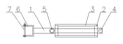
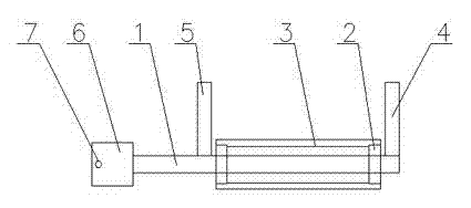
[0018] figure 1 , 2 As shown in the cable laying device, the guide wheel device is a horizontal linear type, including a fixed shaft 1, a bearing 2, a roller 3, an outer baffle 4, an inner baffle 5, a U-shaped opening 6 and a pin 7, and one end of the fixed shaft is connected to a U The U-shaped opening 6 and the pin 7 are plugged into the U-shaped opening 6. The other end of the fixed shaft is connected to the roller 3 through the rolling support of the bearing 2. The end of the roller 3 away from the U-shaped opening is vertically connected to the outer baffle 4 on the fixed shaft. The roller is close to the U-shaped opening. One end of the type opening is vertically connected with an inner baffle plate 5 on the fixed shaft.

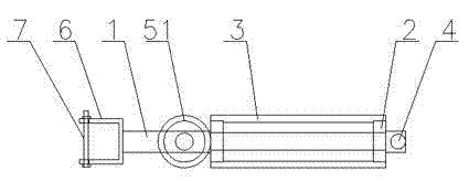
[0019] image 3 , 4 As shown in the cable laying device, the guide wheel device is horizontal and vertical, including a fixed shaft 1, a be...


PUM


Abstract

The invention relates to a cable laying device, comprising fixing shafts, fixing clamp blocks, idler wheels and limiting baffle groups, wherein one ends of the fixing shafts are fixedly connected with the fixing clamp blocks, and the other ends of the fixing shafts are vertically connected with the limiting baffle groups; and the idler wheels are connected on the fixing shaft among the limiting baffle groups through movable supporting of bearings. A guide wheel device for supporting and limiting a cable in a rolling manner is additionally arranged in a cable guide rack. The cable laying device has the advantages of simple structure, and convenience for use; the laying labor intensity is greatly reduced; and the labor is saved. Furthermore, the cable cannot be damaged in a laying process, so that the cable laying quality and the construction speed can be improved.

Description

technical field [0001] The invention relates to a guide wheel device, in particular to a guide wheel device suitable for laying cables. Background technique [0002] On all motor ships, all face the problem that cable laying workload is heavy and input labor is many. The traditional cable laying method is to lay the cable directly on the cable guide frame, which requires a lot of labor, high labor intensity and long construction time for laying the cable. The cable is in direct contact with the surface of the guide frame, and the frictional resistance is large. Cover damage etc. Contents of the invention [0003] In order to solve the deficiencies in the prior art, the object of the present invention is to provide a guide wheel device for cable laying that is simple in structure, easy to use, and can reduce or avoid damage to cables during laying. [0004] In order to achieve the above object, the technical solution adopted by the present invention is: a cable laying ...

Claims


Application Information

Patent Timeline
Patent Type & Authority Applications(China)
IPC IPC(8): H02G1/06
Inventor 杨春杨炯峰冯毅徐美荣
Owner 杨春
Why Eureka
Try Eureka