Synchronous follow current inverter topology without common-mode interference

A common-mode interference and inverter technology, applied in the field of power conversion, can solve the problems of less transformerless inverters, high switching loss, low conversion efficiency, etc., to reduce switching voltage and rated voltage requirements, and reduce freewheeling The effect of low loss and cost

Inactive Publication Date: 2012-10-17
FONRICH NEW ENERGY TECH LTD
View PDF3 Cites 10 Cited by
  • Summary
  • Abstract
  • Description
  • Claims
  • Application Information

AI Technical Summary

Problems solved by technology

However, the inverter topology without a transformer is prone to high-frequency common-mode leakage current between the two sides because there is no isolation between the input and output sides.
Few existing topologies are suitable for transformerless inverters, and each has its own disadvantages
For example, the traditional H-bridge inverter topology has bipolar modulation and unipolar modulation; if bipolar modulation is used, although there is no high-frequency common-mode leakage current problem, its switching loss is high and conversion efficiency is low; If there is a common-mode leakage current problem when using unipolar modulation

Method used


Image

  • Synchronous follow current inverter topology without common-mode interference
  • Synchronous follow current inverter topology without common-mode interference
  • Synchronous follow current inverter topology without common-mode interference

Examples


Embodiment Construction

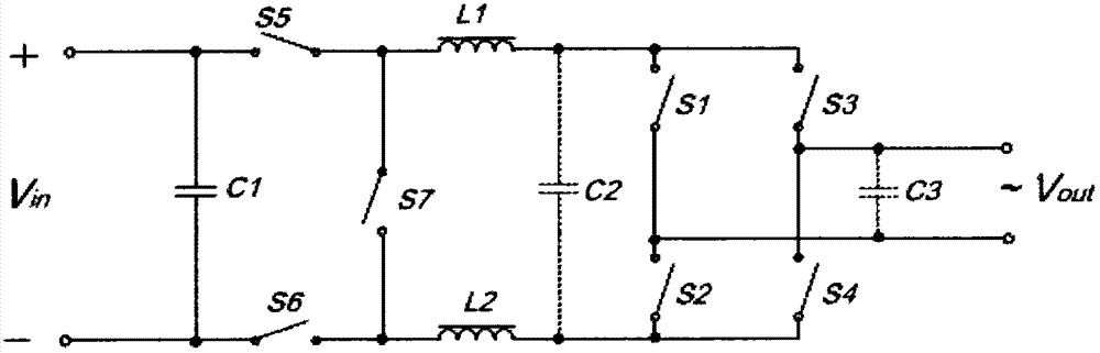
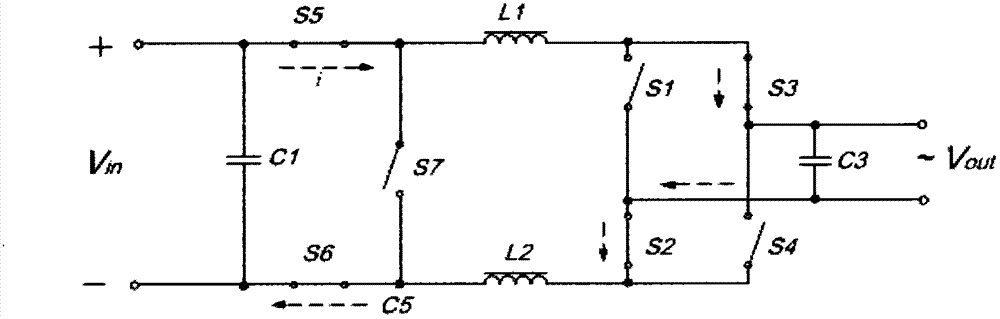
[0018] image 3 , Figure 4 , Figure 5 , Figure 6 is the switch state during operation of the inverter example realized by using the inverter topology of the present invention. image 3 and Figure 4 is the situation when the inverter outputs the AC positive half-wave, Figure 5 and Figure 6 It is the situation when the inverter outputs the negative half-wave of AC. When the inverter outputs the AC positive half-wave, the reversing switches S2 and S3 are kept in the on state; the reversing switches S1 and S4 are kept in the off state, and their blocking voltage is Vout. When the inverter outputs the AC negative half-wave, the reversing switches S1 and S4 are kept in the on state; the reversing switches S2 and S3 are kept in the off state, and their blocking voltage is Vout. The chopper switches S5 and S6 are simultaneously high-frequency switches, and the synchronous freewheeling switch S7 adopts a phase synchronous high-frequency switch opposite to the chopper switc...


PUM


Abstract

A synchronous follow current inverter topology without common-mode interference realizes the high-efficiency inversion of electric energy from direct current to alternating current with lower cost, and meanwhile, the topology is free of the problem of common-mode interference, and the synchronous follow current inverter topology can be conveniently applicable to an inversion system without isolation transformers. The topology adopts the following principle: high-frequency chopping switches are arranged at the positive end and the negative end of the direct current input side and are switched on and off simultaneously, and the duty cycle of switching of the high-frequency chopping switches is modulated to realize the amplitude change of the output voltage; the rear stage of each high-frequency chopping switch is connected with a flat wave inductor, one side of each flat wave inductor is connected with the chopping switch and is also provided with a follow current circuit with a follow current switch, and the follow current of each flat wave inductor is ensured when the chopping switch is switched off; the rear stage of each inductor is provided with an H reversing bridge, and the H reversing bridges carry out reversing according to the frequency of the expected output of an inverter, so that the inversion is realized. With the topology, the switching voltage of a switching tube is reduced, the switching loss of the system is reduced, meanwhile, the topology is free of the problem of common-mode interference, and is applicable to an inversion system without transformers.

Description

technical field [0001] The invention belongs to the field of power conversion, and is a topological structure for converting direct current into alternating current, and can be widely used in inverters that require high common-mode current suppression, such as non-isolated photovoltaic inverters and wind power inverters device etc. Background technique [0002] With the development of industry, the requirements for inverter conversion efficiency are getting higher and higher, especially in new energy power generation, smart grid, flexible AC and DC transmission and other industries. The decisive factor of inverter efficiency is the topology of the inverter, and the quality of the topology determines the efficiency and cost of the inverter. Inverters in many applications, such as photovoltaic grid-connected inverters, often use isolated input and output sides with transformers, so that the electrical isolation between the systems on both sides provides personal protection an...

Claims


Application Information

Patent Timeline
Patent Type & Authority Applications(China)
IPC IPC(8): H02M7/48
CPCH02M7/5387H02M1/007H02M1/123
Inventor 张永
Owner FONRICH NEW ENERGY TECH LTD
Why Eureka
Try Eureka