Insulated gate bipolar transistor (IGBT) driving push-pull circuit

A push-pull circuit and resistor technology, applied in electrical components, electronic switches, pulse technology, etc., can solve the problems of large loss of NPN transistors and PNP transistors, small charge and discharge current peaks, etc., to improve the turn-on and turn-off speed, reduce Loss, the effect of increasing the charge current and discharge current

Inactive Publication Date: 2012-10-17
INST OF ELECTRICAL ENG CHINESE ACAD OF SCI
View PDF4 Cites 8 Cited by
  • Summary
  • Abstract
  • Description
  • Claims
  • Application Information

AI Technical Summary

Problems solved by technology

[0005] The purpose of the present invention is to overcome the shortcoming of the current peak charge and discharge current in the current IGBT push-pull drive circuit, and the excessive loss of the NPN transistor and the PNP transistor, increase the current peak value of the charge and discharge, improve the turn-on and turn-off speed of the IGBT, and reduce the The switching loss of IGBT, and reduce the loss of NPN and PNP transistor, the present invention proposes a kind of new IGBT driving push-pull topology

Method used


Image

  • Insulated gate bipolar transistor (IGBT) driving push-pull circuit
  • Insulated gate bipolar transistor (IGBT) driving push-pull circuit
  • Insulated gate bipolar transistor (IGBT) driving push-pull circuit

Examples


Embodiment Construction

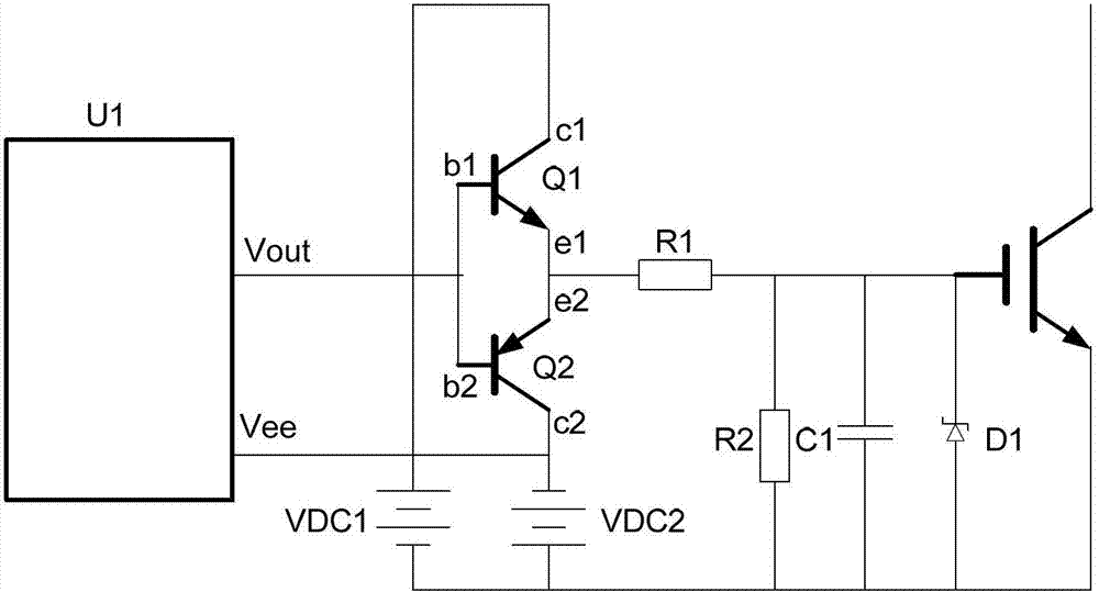
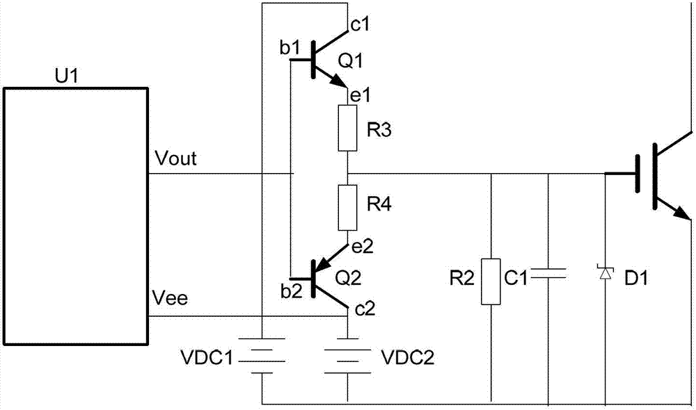
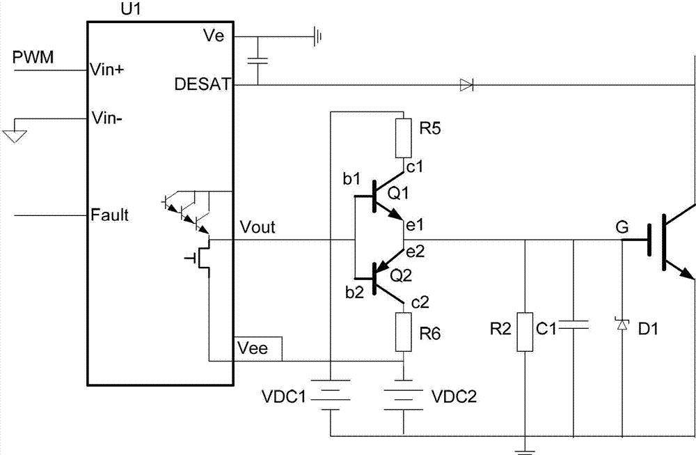
[0014] The IGBT driving push-pull circuit of the present invention is as image 3 As shown, the push-pull circuit mainly includes NPN transistor Q1, PNP transistor Q2, charging resistor R5 and discharging resistor R6. One end of the charging resistor R5 is connected to the positive pole of the input power supply VDC1, and the other end of the charging resistor R5 is connected to the collector c1 of the NPN transistor Q1; the emitter e1 of the NPN transistor and the emitter e2 of the PNP transistor Q2 are connected to one point and connected to the IGBT The gate G is connected. The emitter c2 of the PNP transistor is connected to one end of the discharge resistor R6, and the other end of the discharge resistor is connected to the ground of the power supply VDC2.

[0015] In the present invention, the driving main chip U1 connecting the weak current control signal and the push-pull circuit can be HCPL-316J, ACPL-38JT, EXB841, HCPLJ312, etc., wherein the PWM output terminal Vout...


PUM


Abstract

The invention discloses an insulated gate bipolar transistor (IGBT) driving push-pull circuit, which mainly comprises an NPN triode (Q1), a PNP triode (Q2), a charging resistor (R5) and a discharging resistor (R6), wherein one end of the charging resistor (R5) is connected to an anode of an input power supply (VDC1), and the other end of the charging resistor (R5) is connected to a collector (c1) of the NPN triode (Q1); an emitter (e1) of the NPN triode (Q1) and an emitter (e2) of the PNP triode (Q2) are connected to form a point and connected with a gate (G) of an IGBT; the emitter (e2) of the PNP triode (Q2) is connected with one end of the discharging resistor (R6); and the other end of the discharging resistor (R6) is connected with the ground of a power supply (VDC2). By adoption of a push-pull circuit structure, in the turn-on moment of the IGBT, the NPN triode works in a saturation area, charging current is improved, and the loss of the NPN triode is reduced; and in the turn-off moment of the IGBT, the PNP triode works in the saturation area, discharging current is improved, and the loss of the PNP triode is reduced.

Description

technical field [0001] The invention relates to an IGBT drive circuit, in particular to a push-pull circuit in the IGBT drive. Background technique [0002] With the rapid development of new energy industries such as electric vehicles, solar power, and wind power, the insulated gate bipolar transistor (IGBT) plays an important role as the core component of its conversion, and the prerequisite for high-power IGBT to work reliably must have high-performance IGBT drive circuit, although there are many drive chips on the market to directly drive IGBTs, for high-power IGBTs, an external push-pull circuit is often required to provide the charge required for the IGBT module to be turned on and off. [0003] Currently commonly used drive circuits such as figure 1 shown. Among them, U1 is a driver chip such as HCPL-316J or ACPL-38JT, EXB841, etc., which realizes the connection between the weak current control signal and the push-pull circuit. The PWM output of the driver chip is Vo...

Claims


Application Information

Patent Timeline
Patent Type & Authority Applications(China)
IPC IPC(8): H03K17/04
Inventor 苏伟钟玉林温旭辉
Owner INST OF ELECTRICAL ENG CHINESE ACAD OF SCI
Why Eureka
Try Eureka