
Video quality diagnosis control system and method applied to video surveillance network

A diagnostic method and video monitoring technology, applied in the field of network video, can solve the problems of low manual detection efficiency, high false alarm rate, limited diagnostic types, etc.

Active Publication Date: 2015-12-09
CERTUS NETWORK TECHNANJING
View PDF8 Cites 1 Cited by
  • Summary
  • Abstract
  • Description
  • Claims
  • Application Information

AI Technical Summary

Problems solved by technology

[0007] The purpose of the present invention is to overcome the above-mentioned shortcomings in the prior art, and provide a method of using image processing and pattern recognition technology to automatically process and analyze the content of the front-end video in the video surveillance network, detect and diagnose video faults, thereby solving the low efficiency of manual detection , the problem of slow response, and at the same time, it can overcome the problems of low accuracy rate, high false alarm rate, limited diagnostic types, and small application range of the existing diagnostic system, and realize a high diagnostic accuracy rate, fast response, and low false alarm rate. A video quality diagnosis and control system and method for video surveillance networks with low cost, simple implementation, and a wide range of applications

Method used


Image

  • Video quality diagnosis control system and method applied to video surveillance network
  • Video quality diagnosis control system and method applied to video surveillance network
  • Video quality diagnosis control system and method applied to video surveillance network

Examples


Embodiment Construction

[0057] In order to understand the technical aspects of the present invention more clearly, the following examples are given in detail.

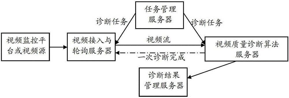
[0058] see figure 1 As shown, it is a schematic structural diagram of a video quality diagnosis and control system applied to a video surveillance network according to the present invention.

[0059] In one embodiment, the system includes: a task management server, a video access and polling server, a diagnosis method server and a diagnosis result management server. in:

[0060] The task management server is used to generate diagnostic tasks and diagnostic method parameters according to user operations;

[0061] The video access and polling server is respectively connected to the task management server and the video surveillance network to obtain the diagnostic task from the task management server, and generate a list of video sources to be diagnosed according to the diagnostic task , acquiring image information of each video source from t...


PUM


Abstract

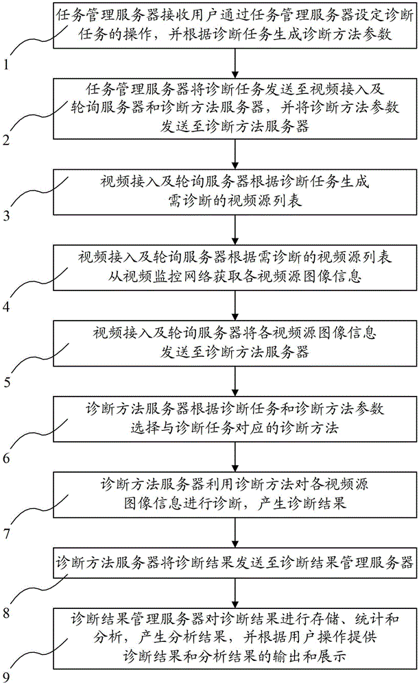
The invention relates to a video quality diagnosis control system and method applied to a video monitoring network, belonging to the technical field of network video. The video quality diagnosis control system comprises a task management server, a video accessing and polling server, a diagnosis method server and a diagnosis result management server. The video quality diagnosis control method comprises the following steps: the task management server sends a diagnosis task to the video accessing and polling server and the diagnosis method server, and sends a diagnosis method parameter to the diagnosis method server; the video accessing and polling server obtain image information of all video sources from the video monitoring network and sends the image information to the diagnosis method server; and the diagnosis method server determines a diagnosis method according to the diagnosis task and the diagnosis method parameter, diagnoses the image information of all video sources, generates a diagnosis result and sends the diagnosis result to the diagnosis result management server. According to the method and the system provided by the invention, video contents of a network front end can be automatically analyzed, and video failures are diagnosed; therefore, the diagnosis accurate rate and the reaction speed are greatly increased and the false positive rate is lowered.

Description

technical field [0001] The invention relates to the technical field of network video, in particular to the technical field of network video quality detection, in particular to a video quality diagnosis control system and method applied to a video monitoring network. Background technique [0002] The traditional technology of video fault inspection using surveillance cameras is almost entirely dependent on manpower. For example, on a network monitoring platform with a scale of 10,000, it takes an average of 1 minute for each person to transfer, detect, and judge a camera, and it takes a person almost 167 hours a week (roughly 21 working days) to complete the detection, which fully exposes the manual method. Problems: 1) The efficiency of the manual method is low; 2) The diagnosis speed is slow, which increases the risk of public safety; because the faulty camera cannot effectively record the event information of the scene. Therefore, in the face of the rapid development of p...

Claims


Application Information

Patent Timeline
Patent Type & Authority Patents(China)
IPC IPC(8): H04N17/02
Inventor 逯利军钱培专董建磊
Owner CERTUS NETWORK TECHNANJING
Learn More