Light emitting diode (LED) driving circuit and control method of LED

A technology of LED drive and drive circuit, applied in the direction of lamp circuit layout, electric light source, electrical components, etc., can solve the problems of large output ripple, severe output voltage jitter, large load current, etc., to avoid ripple and severe jitter Effect

Active Publication Date: 2012-10-17
BCD (SHANGHAI) MICRO ELECTRONICS LTD
View PDF5 Cites 15 Cited by
  • Summary
  • Abstract
  • Description
  • Claims
  • Application Information

AI Technical Summary

Problems solved by technology

In the whole time, the output current of the LED driver circuit in the above-mentioned dimming mode will show two current values. When the current value changes, the load current will change greatly, which will cause severe jitter of the output voltage, resulting in relatively high voltage. large output ripple, which causes a large ripple in the load current

Method used


Image

  • Light emitting diode (LED) driving circuit and control method of LED
  • Light emitting diode (LED) driving circuit and control method of LED
  • Light emitting diode (LED) driving circuit and control method of LED

Examples


Embodiment Construction

[0072] The following will clearly and completely describe the technical solutions in the embodiments of the present invention with reference to the accompanying drawings in the embodiments of the present invention. Obviously, the described embodiments are only some, not all, embodiments of the present invention. Based on the embodiments of the present invention, all other embodiments obtained by persons of ordinary skill in the art without making creative efforts belong to the protection scope of the present invention.

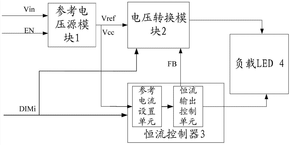
[0073] The embodiment of the present invention discloses an LED drive circuit, such as figure 1 shown, including:

[0074] A reference voltage source module 1, the reference voltage source module 1 receives an external enable signal EN and an external power supply Vin, and generates a reference voltage Vref and an internal stable power supply voltage Vcc;

[0075] A voltage conversion module 2, the voltage conversion module 2 is connected to the reference vol...


PUM


Abstract

The invention discloses a light emitting diode (LED) driving circuit comprising a reference voltage source module, a voltage conversion module connected with the reference voltage source module and a constant-current control circuit which is respectively connected with the reference voltage source module and the voltage conversion module, wherein a load LED is connected between the voltage conversion module and the constant-current control circuit in series, the constant-current control circuit comprises a constant-current output control unit and a reference current setting unit, and the reference current setting unit is respectively connected with the reference voltage source module and the constant-current output control unit; and moreover, current flowing through the constant-current control module is regulated and controlled by the reference current setting unit for slow change, and the constant-current output control unit is respectively connected with the voltage conversion module and the load LED. Therefore, when the current value is changed, the change process of the current value is slow, and load current can not be changed very greatly in unit time, so that the intense fluctuation of output voltage is avoided so as to avoid larger ripples occurring in the load current.

Description

technical field [0001] The invention relates to the technical field of LED lighting, and more specifically, to an LED driving circuit and an LED control method. Background technique [0002] With the development of modern society, the application of electronic products is changing with each passing day, and the market is growing rapidly. Mobile phones, PDA (Personal Digital Assistant, handheld computer), e-books, digital cameras, MP3, GPS (Global Positioning System, global positioning system), digital photo frame And other electronic products, as market hotspots in recent years, have affected people's daily life more and more deeply. The development of these electronic products has also driven and stimulated the development of related products. As LCD (Liquid Crystal Display, liquid crystal display device ) backlight WLED (White Light Emitting Diode, white light-emitting diode) and LED drive circuit demand is also increasing, and many companies at home and abroad have also d...

Claims


Application Information

Patent Timeline
Patent Type & Authority Applications(China)
IPC IPC(8): H05B37/02
CPCH05B37/02H05B45/10
Inventor 孙建波
Owner BCD (SHANGHAI) MICRO ELECTRONICS LTD
Why Eureka
Try Eureka