Electronic part installing method and installing device

A technology of electronic parts and installation methods, applied in the direction of electrical components, electrical components, etc., can solve problems such as easy misalignment, position deviation, and increase in types of holding tools, and achieve the effect of saving space

Active Publication Date: 2012-10-17
FUJI KK
View PDF14 Cites 22 Cited by
  • Summary
  • Abstract
  • Description
  • Claims
  • Application Information

AI Technical Summary

Problems solved by technology

Therefore, there is a problem that the electronic component sucked by the suction nozzle and positioned at a predetermined position on the substrate deviates from the original positioned position due to mechanical vibration during the head replacement operation before performing the pressing operation.
In particular, in light-weight parts such as cover parts, there is a problem that misalignment is likely to occur due to the above-mentioned mechanical vibrations, etc.
[0010] In addition, in Patent Document 2, clamp claws are used as holding tools in order to grasp large electronic components. Therefore, due to the size of the large electronic components to be held, usable holding tools are limited, and the types of holding tools that need to be prepared may increase
If a dedicated clamping claw is used to use the cover part that can be sucked by the suction nozzle, there is a problem that unnecessary equipment costs will be incurred

Method used


Image

  • Electronic part installing method and installing device
  • Electronic part installing method and installing device
  • Electronic part installing method and installing device

Examples


Embodiment Construction

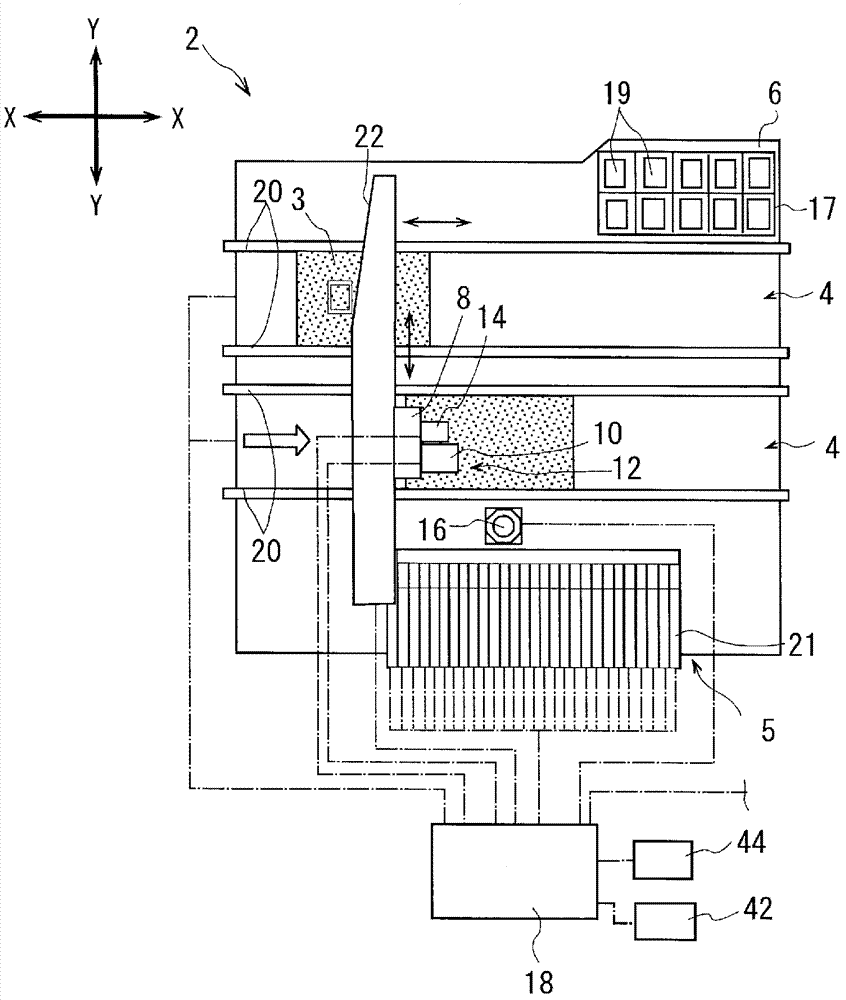
[0045] Hereinafter, 1st Embodiment of the electronic component mounting apparatus which implements the electronic component mounting method of this invention is demonstrated based on drawing.

[0046] Such as figure 1 As shown, the electronic component mounting apparatus 2 includes: a substrate transfer device 4 for carrying a substrate 3 into a loading position and positioning it at a predetermined position; a component supply device 5; Device 12 and mark identification camera 14, the mobile platform 8 is supported to be able to move in the horizontal direction relative to the base platform 6, that is, the X direction and the Y direction; the part identification camera 16 fixed on the base platform 6; The control device 18 for the installation performed by the carrier device 12.

[0047] The substrate transfer device 4 is a so-called double-conveyor type, and each conveyor includes: parallel conveyor belts (not shown), arranged side by side along the guide rail 20 extending ...


PUM


Abstract

The invention relates to an electronic part installing method and an installing device, which can conduct positioning on cover parts and install the cover parts behind a substrate and prevent dislocation before fixing through pressing and reduce tool variety. The electronic part installing device installs upper and lower moving components having pressing parts at a part transferring device and can drive the upper and lower moving components up and down. The pressing part is pressed and positioned at a cover part of regulated position. The electronic part installing method comprises a substrate moving and positioning process which is to move the substrate by a substrate moving device and to conduct positioning on the substrate; a cover part positioning and carrying process which is to select the cover part by means of a part transferring device through absorption and to conduct positioning and carrying on the cover parts to a regulated position of the positioned substrate in the substrate moving and positioning process; a pressing and assembling process which is to immediately drive the upper and lower moving components and press the cover parts by the pressing part after the cover parts are positioned and disposed at the regulated position by means of the part transferring device, and thereby an engaging mechanism of the cover part can be engaged with an engaged mechanism disposed at the substrate.

Description

technical field [0001] The present invention relates to an electronic component mounting method for mounting an electronic component on a substrate by pressing a cover component that covers the electronic component mounted on the substrate, and a mounting device using the method. Background technique [0002] Conventionally, electronic components mounted by electronic component mounting devices are easily affected by electromagnetic waves or heat. Recently, in order to prevent such influences, shielding covers or mounting cases are increasingly attached to substrates in mobile phones and personal computers. Cover parts such as shield covers are not attached to the part where paste-like solder is printed like electronic parts, and are heated and fixed to the substrate in a reflow furnace. Since the substrates are engaged, after the covered electronic components are mounted, the operator presses and inserts them with his hands. In such a manual operation, assembly may be devi...

Claims


Application Information

Patent Timeline
Patent Type & Authority Applications(China)
IPC IPC(8): H05K13/04
Inventor 野田明宏斋藤达美久保田知克内藤真治
Owner FUJI KK
Why Eureka
Try Eureka