Machine tool, especially hand-held machine tool

A hand-held machine tool and machine tool technology, which is applied in the direction of manufacturing tools, metal processing mechanical parts, metal processing equipment, etc., can solve the problems of inconvenience, tedious work operation, and the use of mechanical auxiliary devices is easily limited.

Inactive Publication Date: 2012-10-17
ROBERT BOSCH GMBH
View PDF5 Cites 4 Cited by
  • Summary
  • Abstract
  • Description
  • Claims
  • Application Information

AI Technical Summary

Problems solved by technology

[0003] In operation, such mechanical aids are limited in their range of use, are often cumbersome and often cause inconveniences in the running of the work

Method used


Image

  • Machine tool, especially hand-held machine tool
  • Machine tool, especially hand-held machine tool
  • Machine tool, especially hand-held machine tool

Examples


Embodiment Construction

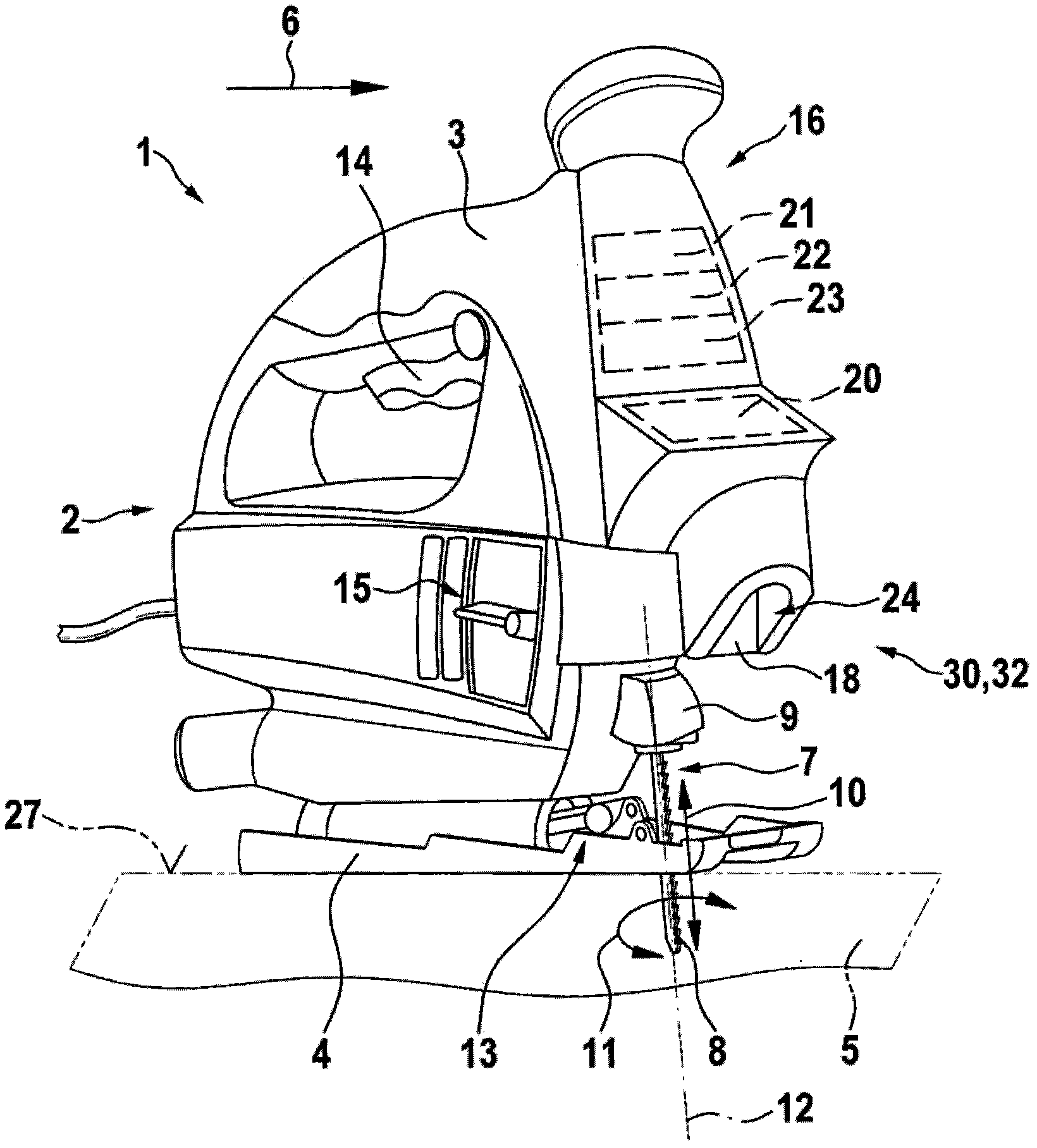
[0014] figure 1 Firstly, the basic structure of a hand-held jigsaw 2 as an example of a power tool 1 is shown. The jigsaw 2 has a housing 3 which is movably supported on the surface of a workpiece 5 via a base plate 4 . The jigsaw 2 has a saw blade 8 as a working tool 7 for which a machining plane is predetermined by its shape. The saw blade 8 is held in the tool receptacle 9 and is driven reciprocally in the direction of the arrow 10 . The axis of reciprocation of the saw blade 8 coincides in this figure with the axis of rotation 12 about which the saw blade 8 (as indicated by the arrow 11 ) is rotatable (with reference to the described embodiment). Via the rotational position of the saw blade 8 the corresponding sawing direction can be set as the working direction. The working direction indicated by the arrow 6 corresponds to the straight working direction of the jigsaw 2 , which corresponds to the working plane of the saw blade 8 in the middle position of the saw blade, ...


PUM


Abstract

An especially hand-held machine tool, preferably designed as a jigsaw (2), comprises a distance measuring unit (29) for the contactless detection of a section (43) of a specified path and for visualizing a working path (33) corresponding to the specified path (31) and / or for aligning the machine tool (1) including its working tool (7) with the working path (33) corresponding to the shape of the specified path (31) by means of an adjusting device.

Description

technical field [0001] The invention relates to a power tool, in particular a hand-held power tool, according to the preamble of claim 1 or 2 . Background technique [0002] Power tools of the above-mentioned type are often used in practice (in particular also as jigsaws) and for their working tools follow a working path which is offset from a preset path extending laterally offset relative to the power tool. work with an auxiliary device. The auxiliary device comprises a guide shoe arranged laterally protrudingly relative to the machine, which is arranged on a support adjustable relative to the power tool and which is displaceable along a preset path parallel to the working track in guided contact with the . For example, workpiece edges, guide plates, etc. can be used as preset paths. [0003] In operation, such mechanical aids tend to be limited in their range of use, are often cumbersome and often cause inconveniences in the running of the work. This requires addition...

Claims


Application Information

Patent Timeline
Patent Type & Authority Applications(China)
IPC IPC(8): B23Q17/24B23D49/08B23D59/00
CPCB23Q17/2404B23Q17/24B23D59/001Y10T83/9454
Inventor T·克尔德J·普拉策J·克格尔
Owner ROBERT BOSCH GMBH
Why Eureka
Try Eureka