Multiband antenna structure

An antenna structure, multi-band technology, used in antennas, resonant antennas, electrical short antennas, etc., can solve problems such as insufficient solutions

Inactive Publication Date: 2012-10-17
PULSE FINLAND
View PDF6 Cites 10 Cited by
  • Summary
  • Abstract
  • Description
  • Claims
  • Application Information

AI Technical Summary

Problems solved by technology

However, if the device must also be used in WCDMA7 systems, whos

Method used


Image

  • Multiband antenna structure
  • Multiband antenna structure
  • Multiband antenna structure

Examples


Embodiment Construction

[0020] Figures 1a and 1b have already been described in connection with the description of the prior art.

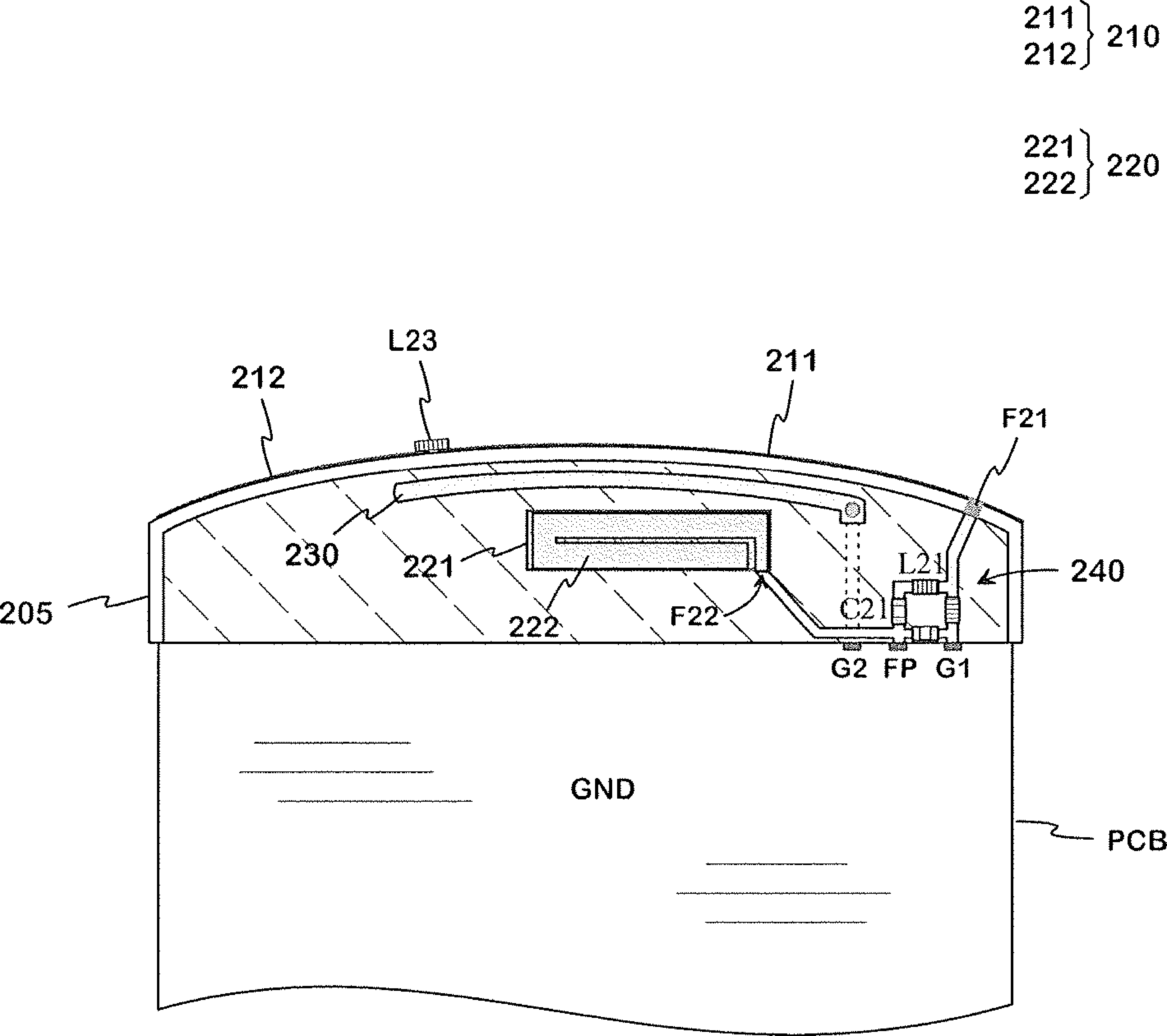
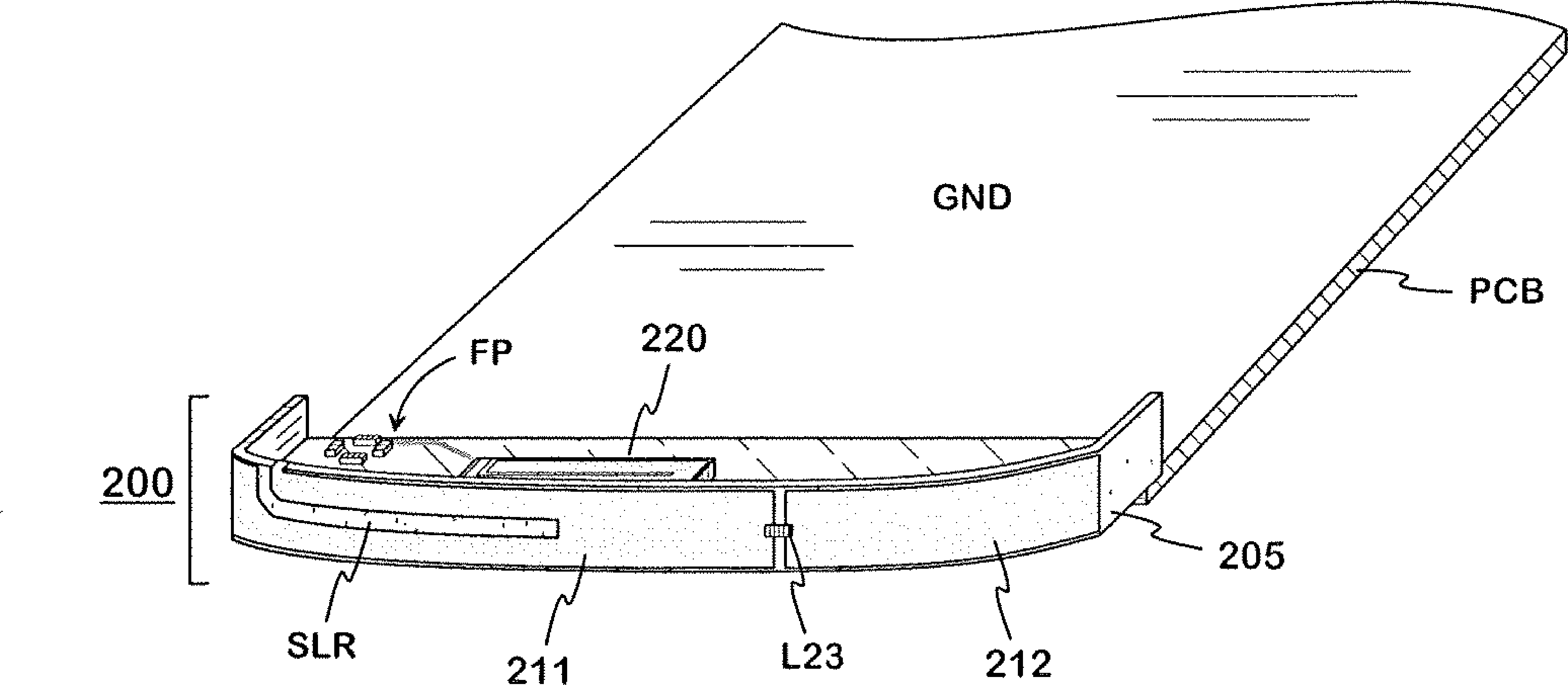
[0021] exist Figure 2a with 2b In is an example of a multi-band antenna structure according to the present invention. It is located at one end of the circuit board PCB of the radio unit, outside the board and seen from the front as Figure 2a perspective in and in Figure 2b Middle is viewed from above, or from the side of the ground plane perpendicular to it. The upper surface of the circuit board is mostly the signal ground GND of the radio, which also serves as a ground plane for the local antenna. The antenna structure has three separate operating bands: the lowest operating band, the upper operating band and the highest operating band, wherein the lowest operating band is in the low band and the latter two are in the high band. The structure includes four radiators: a main radiator 210, a second radiator 222, a parasitic radiator 230 and a slot radiator SLR. Th...


PUM

PropertyMeasurementUnit
Inductanceaaaaaaaaaa

Abstract

An antenna structure intended for small-sized mobile terminals. It comprises a main radiator (210) for implementing the lowest operating band and other radiators for implementing at least one operating band in the high band. The structure comprises also a matching circuit, by which a double resonance is implemented for the main radiator in the range of the lowest operating band and the isolation is improved between the main radiator and another radiator. A reactive element (L23) is joined to the main radiator so that its electric size decreases in the high band and increases in the low band. The former matter strengthens the resonances in the high band and thus results in rise in the efficiency in the high band.

Description

technical field [0001] The invention relates to a multi-band antenna structure intended especially for small mobile terminals. Background technique [0002] In mobile terminals that fit in pockets, the antenna is usually placed inside the cover of the device, in which case the small available space complicates the antenna design. The difficulty increases significantly when the device has to be able to operate according to several radio systems, such as the different GSM systems (Global System for Mobile Communications). The smallness of the ground plane of the device (which is at the same time the ground plane of the antenna) is a degrading factor for the antenna function especially in the frequency range below 1 GHz. [0003] A solution that satisfies the requirements inevitably has a relatively complex radiator structure or more than one separate local antenna. Figures 1a and 1b show an example of such a multiband antenna known from publication WO 2008 / 081077. The anten...

Claims


Application Information

Patent Timeline
IPC IPC(8): H01Q5/01H01Q21/30H01Q9/30H01Q1/24H01Q5/10
CPCH01Q9/0421H01Q9/30H01Q1/243H01Q5/0041H01Q5/0058H01Q5/0062H01Q21/30H01Q5/335H01Q5/371H01Q5/378
Inventor R.库奥纳诺贾
Owner PULSE FINLAND
Why Eureka
Try Eureka