Automatic feeding trough

A feeding trough and automatic technology, applied in animal feeding devices, applications, animal husbandry, etc., can solve the problems of inconspicuous feed shifting effect, affecting the balance of live pigs, and uneven feeding of feeding basins, etc., and is easy to implement , Simple structure, smooth discharge effect

Active Publication Date: 2012-10-24
COMAX LIVESTOCK TECH JIANGSU CO LTD
View PDF10 Cites 10 Cited by
  • Summary
  • Abstract
  • Description
  • Claims
  • Application Information

AI Technical Summary

Problems solved by technology

[0002] The feeders previously used in the animal husbandry industry, especially the feeders suitable for feeding pigs, often have the simplest structure just a square or round trough. Although this kind of trough has a simple structure and low manufacturing cost, the pigs eat It is easy to remove the feed to the outside of the feeding trough, and the pigs often don’t eat the leftover feed, so it causes a lot of waste of feed
[0003] In response to the above problems, the prior art has been improved, such as a novel feeder disclosed in the utility model patent with the authorized announcement number CN201078948Y, which includes a material basin and a material bucket, and a protruding cone is arranged in the middle of the material basin. The pot is equipped with a cage-shaped fixing frame, and a feeding key is movably installed on the protruding cone. The number of feeding keys corresponds to the number of columns in the fixing frame. Feeding bar; the feeding button installed on the cone of the feeding basin is fixedly connected with the feeding bar, which will cause the rotation of the feeding bar when the pigs eat and hit the feeding button, so that the feed will shake down to the feeder along the cone. In the basin, the purpose of automatic feeding is achieved; however, in this automatic feeding method, since there are multiple feeding keys, and the feeding is done from the gap between the periphery of the cone and the inner wall of the barrel, the feeding It is relatively scattered, which is equivalent to dividing the feeding basin into multiple feeding areas. Therefore, when a feeding button is damaged, the feeding in each area of ​​the feeding basin will be uneven, thus affecting the growth balance of pigs
[0004] Another example is a kind of automatic feeding trough disclosed by the utility model patent whose authorization notification number is CN201131220Y. There is a shifting fork at the side, and the shifting fork is set on the supporting standpipe; although it can realize automatic feeding, however, because the part of the shifting fork in the storage hopper is erected in the storage hopper, therefore, its When turning, the horizontal contact surface of the feed at the feeding port of the storage hopper is small, and the vertical contact surface is large. Therefore, the stirring effect on the feed is not obvious, resulting in unsmooth feeding and prone to blockage.
[0005] To sum up, the automatic feeding trough in the prior art may easily lead to uneven feeding or unsmooth feeding and blocking of feeding in the feeding basin.

Method used


Image

  • Automatic feeding trough
  • Automatic feeding trough
  • Automatic feeding trough

Examples


Embodiment 1

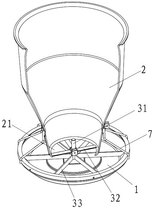
[0036] Embodiment 1: as figure 1 As shown, an automatic feeding trough includes a trough 1 and a barrel 2 fixedly connected to the top of the trough 1 through a fixing frame 7 .

[0037] The middle part of the material trough 1 is rotatably connected with a rotating shaft 31. A rotating arm 32 close to the discharge port 21 and extending outward along the middle part of the discharging port 21 is installed on the rotating shaft 31. The part below the rotating arm 31 is installed on the rotating shaft 31. There is a driving lever 33 for driving the rotating arm 32 to rotate through the rotating shaft 31 .

[0038] When in use, the live pig will hit the driving lever 33, so that the driving lever 33 drives the rotating arm 31 to swing, thereby realizing automatic feeding.

Embodiment 2

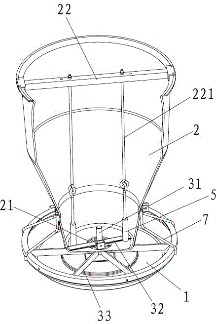
[0039] Embodiment 2: as figure 2 As shown, an automatic feeding trough includes a trough 1 and a barrel 2 fixedly connected to the top of the trough 1 through a fixing frame 7; the bottom surface of the barrel 2 is provided with a discharge port 21.

[0040] The middle part of the material trough 1 is rotatably connected with a rotating shaft 31. A rotating arm 32 close to the discharge port 21 and extending outward along the middle part of the discharging port 21 is installed on the rotating shaft 31. The part below the rotating arm 31 is installed on the rotating shaft 31. There is a driving lever 33 for driving the rotating arm 32 to rotate through the rotating shaft 31 .

[0041] The rotating arm 31 is located above the bottom surface of the material barrel 2, and is close to the bottom surface of the material barrel 2, and the free end of the rotating arm 31 extends outside the edge of the discharge port 21, and is close to the inner wall of the material barrel 2, so as ...

Embodiment 3

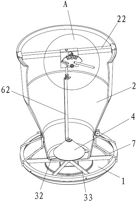
[0046] Embodiment 3: as Figure 3-5 As shown, an automatic feeding trough includes a trough 1 and a barrel 2 fixedly connected to the top of the trough 1 through a fixing frame 7; the bottom surface of the barrel 2 is provided with a discharge port 21.

[0047] The middle part of the material trough 1 is rotatably connected with a rotating shaft 31. A rotating arm 32 close to the discharge port 21 and extending outward along the middle part of the discharging port 21 is installed on the rotating shaft 31. The part below the rotating arm 31 is installed on the rotating shaft 31. There is a driving lever 33 for driving the rotating arm 32 to rotate through the rotating shaft 31 .

[0048] The rotating arm 31 is located above the bottom surface of the material barrel 2, and is close to the bottom surface of the material barrel 2, and the free end of the rotating arm 31 extends outside the edge of the discharge port 21, and is close to the inner wall of the material barrel 2, so a...


PUM


Abstract

The invention relates to the technical field of animal husbandry equipment, in particular to an automatic feeding trough, which is particularly suitable for being used for feeding pigs. The automatic feeding trough is realized through the following technical scheme that the automatic feeding trough comprises a feed trough, a feed barrel and a pulling rod structure, wherein the feed barrel is positioned above the feed trough and is provided with a feed outlet, the pulling rod structure is used for realizing the automatic feeding and comprises a rotating shaft, a rotating arm and a driving rod,the rotating arm is arranged on the rotating shaft, is near the feed outlet and outwards extends along the middle of the feed outlet, and the driving rod is arranged on the rotating shaft and is usedfor driving the rotating arm to rotate through the rotating shaft. The automatic feeding trough has the advantages that the baiting is uniform and smooth, and in addition, the blockage cannot easily occur.

Description

technical field [0001] The invention relates to the technical field of animal husbandry equipment, in particular to an automatic feeding trough, which is especially suitable for feeding pigs. Background technique [0002] The feeders previously used in the animal husbandry industry, especially the feeders suitable for feeding pigs, often have the simplest structure just a square or round trough. Although this kind of trough has a simple structure and low manufacturing cost, the pigs eat When it is time, it is easy to remove the feed to the outside of the trough, and the pigs often don't eat the rest of the feed, so a lot of feed waste is caused. [0003] In response to the above problems, the prior art has been improved, such as a novel feeder disclosed in the utility model patent with the authorized announcement number CN201078948Y, which includes a material basin and a material bucket, and a protruding cone is arranged in the middle of the material basin. The pot is equip...

Claims


Application Information

Patent Timeline
Patent Type & Authority Applications(China)
IPC IPC(8): A01K5/02
Inventor 陈新华
Owner COMAX LIVESTOCK TECH JIANGSU CO LTD
Why Eureka
Try Eureka