Air compressor device for glue supplement and air inflation

An air compressor and glue filling technology, which is applied in transportation and packaging, vehicle maintenance, vehicle maintenance/repair, etc., can solve problems such as time-consuming operation, stickiness, and troublesome rescue operations

Active Publication Date: 2012-10-24
周文三
View PDF6 Cites 7 Cited by
  • Summary
  • Abstract
  • Description
  • Claims
  • Application Information

AI Technical Summary

Problems solved by technology

Since the length of the conventionally installed pipe body in the glue filling tank is lower than the height of the chemical glue layer in the glue filling tank, that is to say, the remote opening of the pipe body blocked by the plug is hidden inside the chemical glue layer, The remote opening of the pipe body is an important entrance for compressed air to enter the interior of the glue filling tank from the outside. Under this structural design, the compressed air must first pass through the chemical glue layer filled in the glue filling tank when entering the glue filling tank. Then reach the clearance space at the top of the tank on the upper surface, and wait until enough air pressure is accumulated to force the chemical glue to flow from top to bottom, so that the chemical glue flows out from the glue outlet pipe. This kind of operation method requires Overcome the resistance of the chemical glue in the glue tank of the original product, which has a certain height, especially the chemical glue is not only quite viscous, but also in the case of glue filling and tire repair in severe cold areas It is obviously time-consuming for the air compressor to inject glue into the damaged tire and inflate it, which leads to quite troublesome and inconvenient rescue operations
[0003] In view of this, the present inventor has made in-depth ideas on the many shortcomings and inconveniences caused by the imperfect structural design of the above-mentioned air compressor device, and actively researched and improved the trial production and developed a design that is even at minus 40 degrees Celsius. It is a device that can efficiently and quickly repair and inflate damaged tires in a low temperature environment

Method used


Image

  • Air compressor device for glue supplement and air inflation
  • Air compressor device for glue supplement and air inflation
  • Air compressor device for glue supplement and air inflation

Examples


Embodiment Construction

[0049] In order to further explain the technical solution of the present invention, the present invention will be described in detail below through specific embodiments.

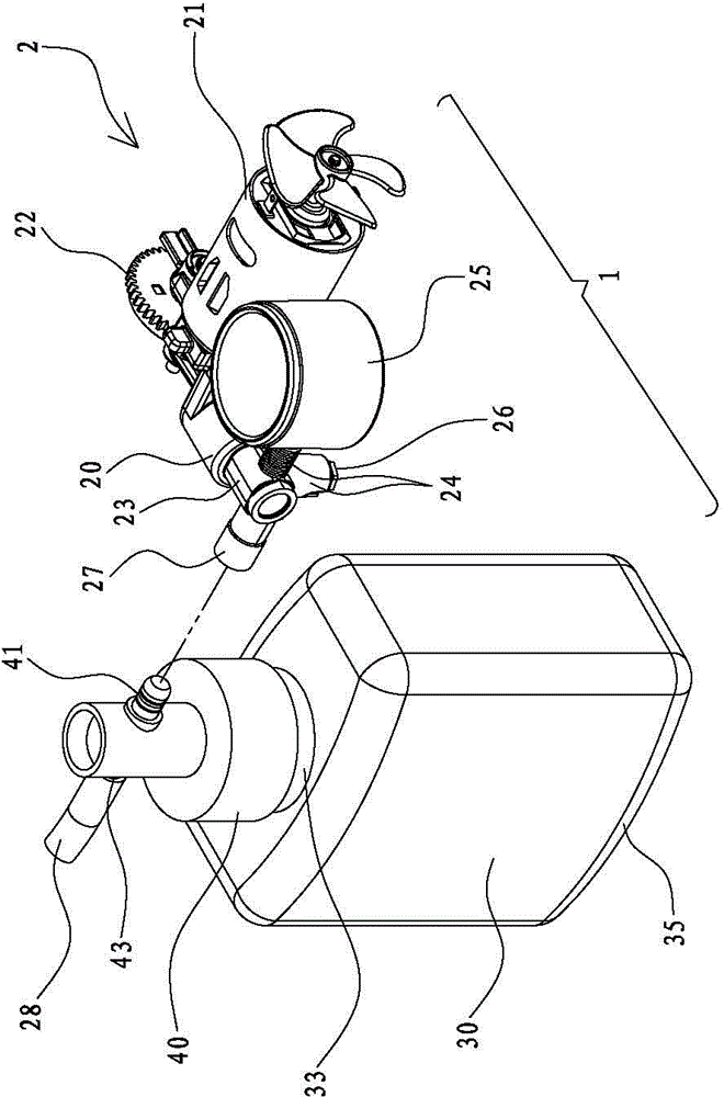
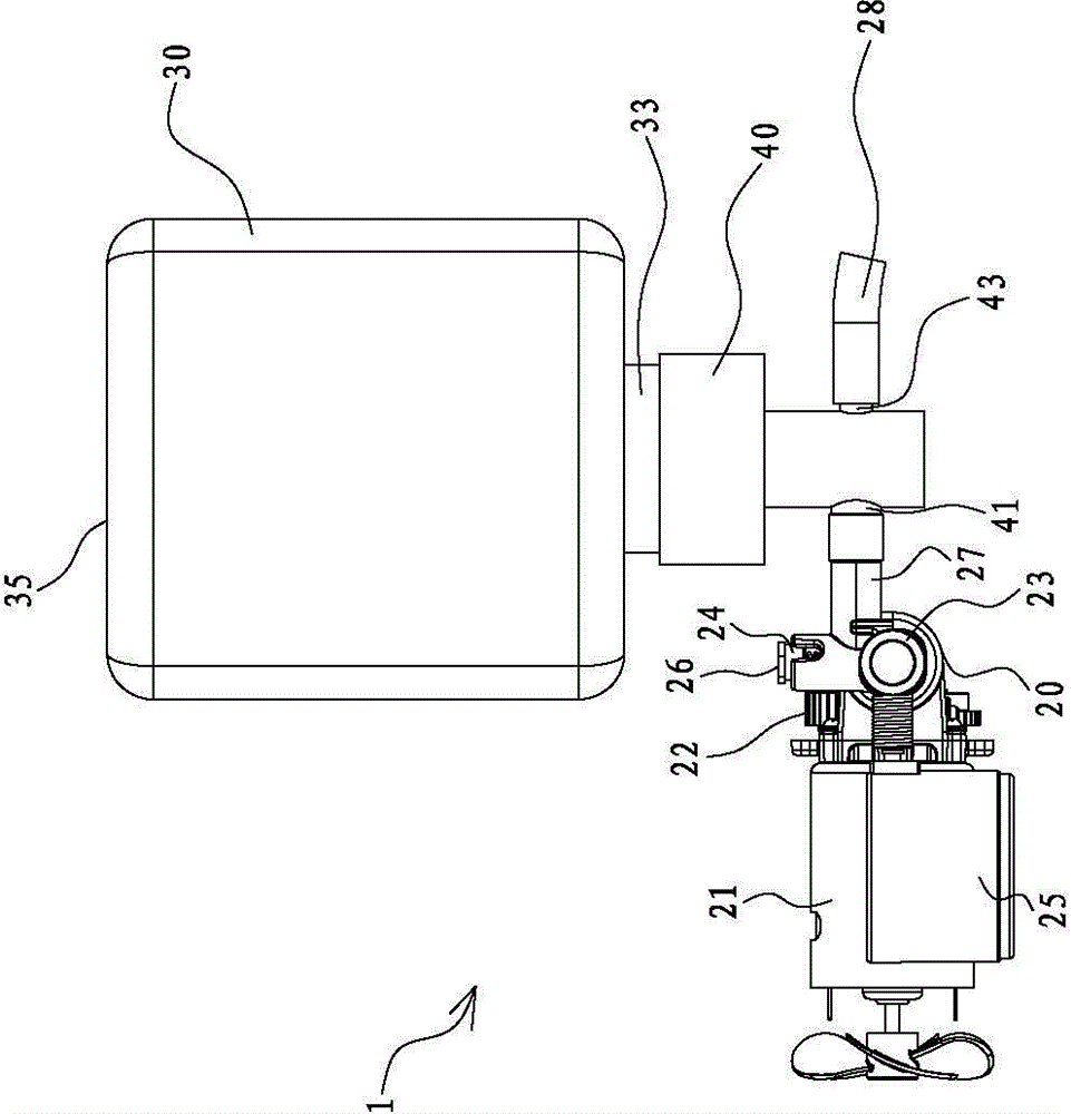
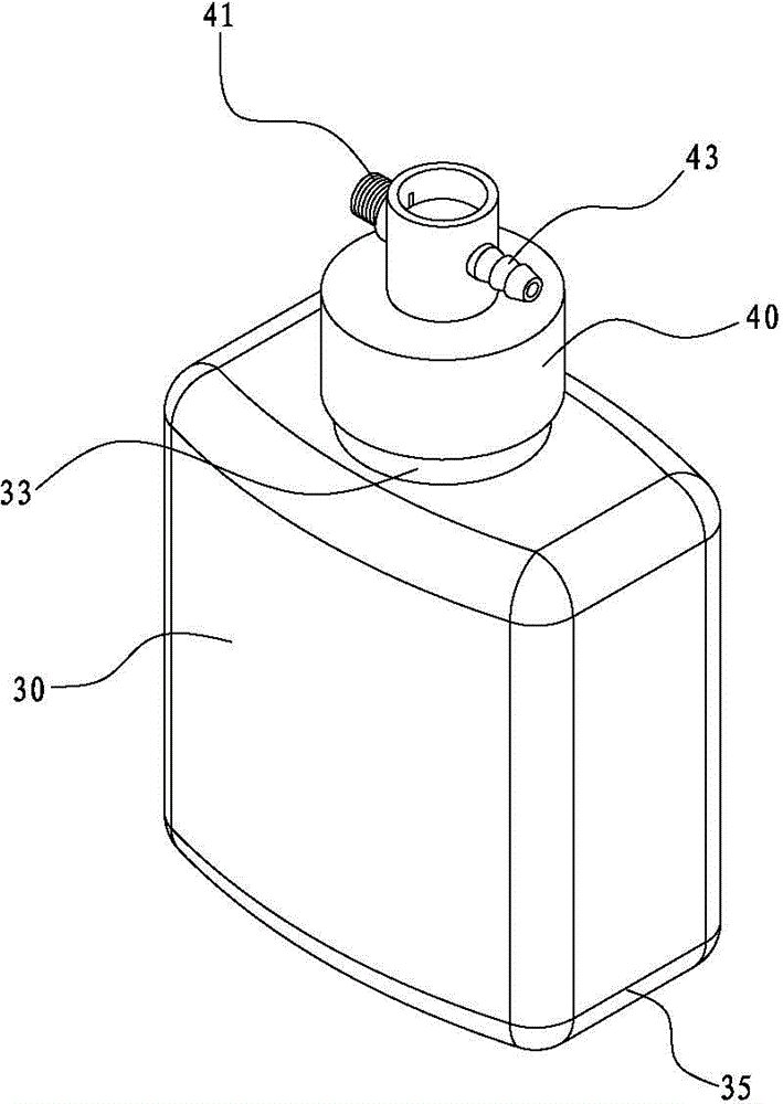
[0050] Please refer first figure 1 , figure 2 , image 3 and Figure 5 The air compressor device 1 for replenishing and charging in the present invention includes an air compressor 2, a replenishing tank 30, and a cover 40. The air compressor 2 has a cylinder chamber 20 in which a piston body (not shown in the figure) can be accommodated. A motor 21 can actuate the gear 22 and drive the piston body to reciprocate up and down in the cylinder chamber 20. The compressed air can be sent out through the air outlet manifold 27 of the air storage seat 23, and other manifolds 24 can be provided on the air storage seat 23. The pressure gauge 25, the safety valve 26, and the above air compressor structure can be connected to the manifold 24 It is a typical structure, so it will not be described in further detail.

[0051...


PUM


Abstract

The invention discloses an air compressor device for glue supplement and air inflation, which can be used for the glue supplement and the air inflation of a damaged tyre. The device comprises an air compressor and a glue supplementing pot containing a chemical glue solution therein, the air inlet end tube of a cover is connected with the air outlet branch tubes of the air compressor to accept compressed air, and the glue outlet end tube of the cover is connected to the air tap of the damaged tyre to convey the chemical glue solution to the damaged tyre. One end of a tube having a length greater than the solution level of the chemical glue solution is connected to the cover, and the other end of the tube is provided with at least one pore. When the glue supplementing pot is in a normal use state, the height of the pore is higher than the initial height of the chemical glue solution in an original state to make the compressed air enter a clearance space at the top of the glue supplementing pot through directly going through the pore of the tube, and downward squeeze the upper surface of the chemical glue solution to send out the chemical glue solution through a glue outlet end tube, so the tyre repair and air inflation time can be substantially shortened.

Description

Technical field [0001] The invention relates to an air compressor device for repairing and inflating rubber, in particular to an air compressor device capable of repairing and inflating damaged tires. Background technique [0002] At present, the conventional air compressor device for repairing and inflating broken tires, the main components of which include an air compressor, an independent rubber replenishing tank containing chemical glue, and a screw-fitted rubber replenishing tank. The cover body is provided with an air inlet end tube and a glue outlet end tube. A tube body with open ends can be connected to the cover body by one end opening, and a plug is closed at the other end opening of the tube body. In the case of non-tire repair operations, the plug blocks the tube body so that the chemical glue will not flow backwards through the tube body channel to the glue outlet tube of the cover body and flow out of the glue tank. When rubber filling and tire repair operations a...

Claims


Application Information

Patent Timeline
Patent Type & Authority Applications(China)
IPC IPC(8): B29C73/02B60S5/04
CPCB29C73/166
Inventor 周文三
Owner 周文三
Why Eureka
Try Eureka