
Automatic temperature control system and control method thereof

A technology of temperature control system and temperature control method, which is applied in the directions of railway car body parts, railway vehicle heating/cooling, transportation and packaging, etc., and can solve the problem that the temperature cannot be automatically controlled by personnel density.

Inactive Publication Date: 2012-10-24
SHANGHAI SIMCOM LTD
View PDF8 Cites 18 Cited by
  • Summary
  • Abstract
  • Description
  • Claims
  • Application Information

AI Technical Summary

Problems solved by technology

[0003] The technical problem to be solved by the present invention is to provide an automatic temperature control system and its control method to solve the problem that the existing technology cannot automatically perform temperature control according to the real-time temperature and personnel density of the place to be adjusted

Method used


Image

  • Automatic temperature control system and control method thereof
  • Automatic temperature control system and control method thereof

Examples


Embodiment Construction

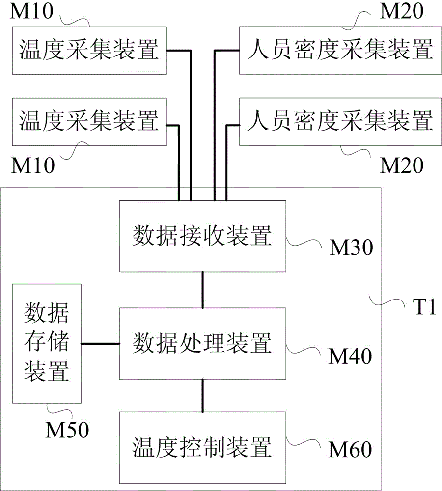
[0025] The specific implementation of the automatic temperature control system and its control method provided by the present invention will be described in detail below in conjunction with the accompanying drawings. The present invention can be used for the temperature control of the compartments of subways and other public transport vehicles, venues, exhibition centers and places waiting for adjustment. In order to make the description of this embodiment simple and clear, only the temperature control of the subway car is used as an example for description, and the temperature control principles of other places to be adjusted are the same as the temperature control principles of the subway car.

[0026] Reference attached figure 1 , a structural schematic diagram of the automatic temperature control system of the present invention, including a temperature control terminal T1, a plurality of temperature acquisition devices M10 and a plurality of personnel density acquisition d...


PUM


Abstract

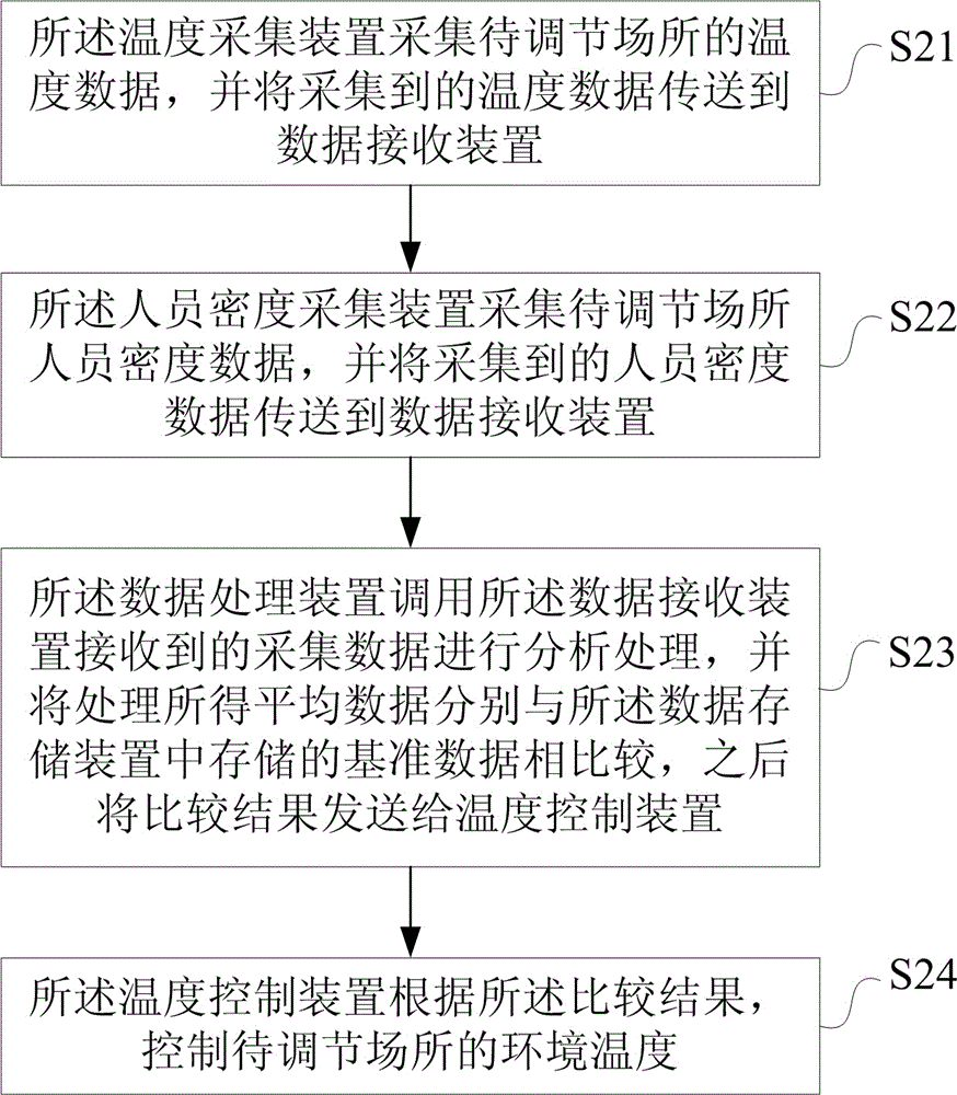
The invention relates to an automatic temperature control system. The automatic temperature control system comprises a temperature control terminal, a plurality of temperature collecting devices and a personnel density collecting device. The temperature control terminal comprises a data receiving device, a data processing device, a data storage device and a temperature control device. The temperature collecting devices and the personnel density collecting device are connected with the data receiving device to collect temperature data and personnel density data in a field to be adjusted, respectively and transmit the data collected to the data receiving device. The data processing device is respectively connected with the data receiving device, the data storage device and the temperature control device for analyzing and processing the collected data received by the data receiving device and comparing the average temperature and personnel density data processed with a reference temperature and personnel density data stored in the data storage device respectively, and sends a comparison result to the temperature control device. The temperature control device is used for controlling the environmental temperature of the field to be adjusted according to the comparison result.

Description

technical field [0001] The invention relates to the technical field of environmental parameter control, in particular to an automatic temperature control system and a control method thereof. Background technique [0002] The current urban roads are becoming more and more crowded, therefore, more and more people choose to travel by urban public transport, but the urban public transport industry is not optimistic. Taking the subway as an example, there are a lot of people during the rush hour, and the subway cars are very crowded. Because the subway car is a closed system, it is usually necessary to set up an air-conditioning system, but the existing air-conditioning system cannot automatically adjust according to the temperature in the car and the number of people in the car. Take summer as an example, the subway is very crowded during the commute rush hour, causing the inside of the train to be stuffy and sweaty, but during free time, when there are very few passengers, the...

Claims


Application Information

Patent Timeline
Patent Type & Authority Applications(China)
IPC IPC(8): B61D27/00
Inventor 孙贵香郑爱群
Owner SHANGHAI SIMCOM LTD
Learn More