
Heat source for radiant heating system

a radiant heating and heat source technology, applied in indirect heat exchangers, lighting and heating apparatus, heating types, etc., can solve the problems of affecting the efficiency of the heating system, so as to achieve the effect of lowering the temperature of the air

Active Publication Date: 2008-08-12
MACPHERSON ENG
View PDF34 Cites 9 Cited by
  • Summary
  • Abstract
  • Description
  • Claims
  • Application Information

AI Technical Summary

Benefits of technology

"The present invention provides a secondary heating system for buildings with a primary heating system that uses a forced air furnace. The secondary system uses a radiant heating loop that heats a desired area by circulating heating fluid through the loop. The heating fluid is heated by the hot air flow from the forced air furnace and then circulated through the radiant heating loop. The system can also cool down the area surrounding the radiant heating loop if it is cooler than the desired area. The invention is particularly useful for in-floor systems embedded in concrete slabs of basements. The technical effects of the invention include improved efficiency, better control over heating, and improved comfort in the building."

Problems solved by technology

Additionally, using forced air heating alone often involves some disadvantages.
A common disadvantage of using a forced air furnace alone is that the heated air in a room, because it has a tendency to rise, can often leave the floor of the room cooler than the surrounding air.
This problem is further exaggerated when the building comprises multiple floors, such as a main floor and a basement.
Basements also typically have ceiling diffusers that are used to supply the heated air to spaces, which further exaggerates the problems with the heated air in a room tending to rise because the ceiling diffusers introduce the heated air into the basement space at ceiling level.
The disadvantage of using a secondary radiant heating system that operates using circulating heating fluid is that there must be a heat source for heating the heating fluid to be circulated through the radiant heating system.
The disadvantage of using a boiler is that boilers are more complex to design, operate and maintain than forced air furnaces.
Additionally, there is the added expense of the boiler which is purchased in addition to the forced air furnace that will be used as the primary source of heating, cooling and ventilation that may be already in place.

Method used


Image

  • Heat source for radiant heating system
  • Heat source for radiant heating system
  • Heat source for radiant heating system

Examples


Embodiment Construction

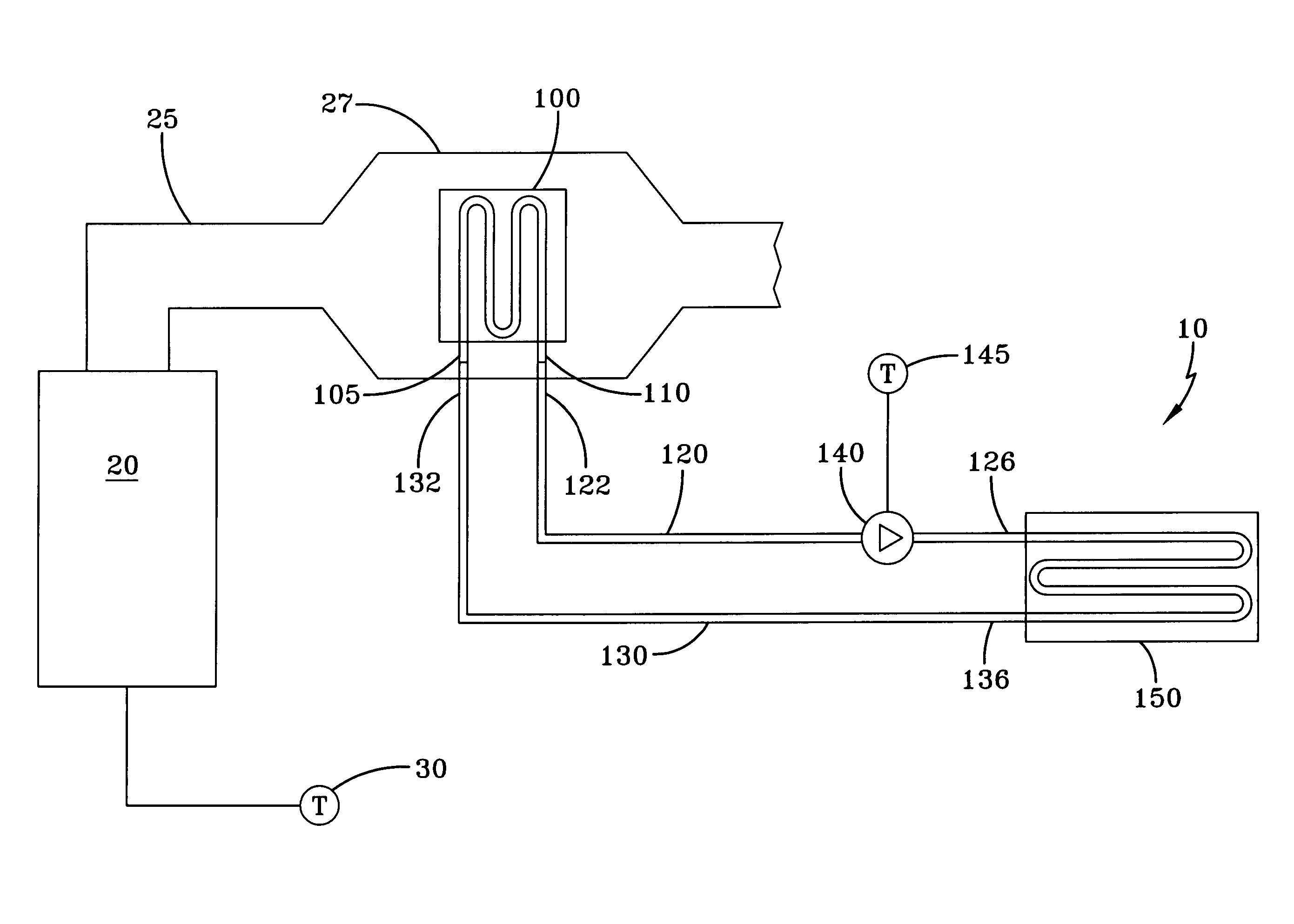
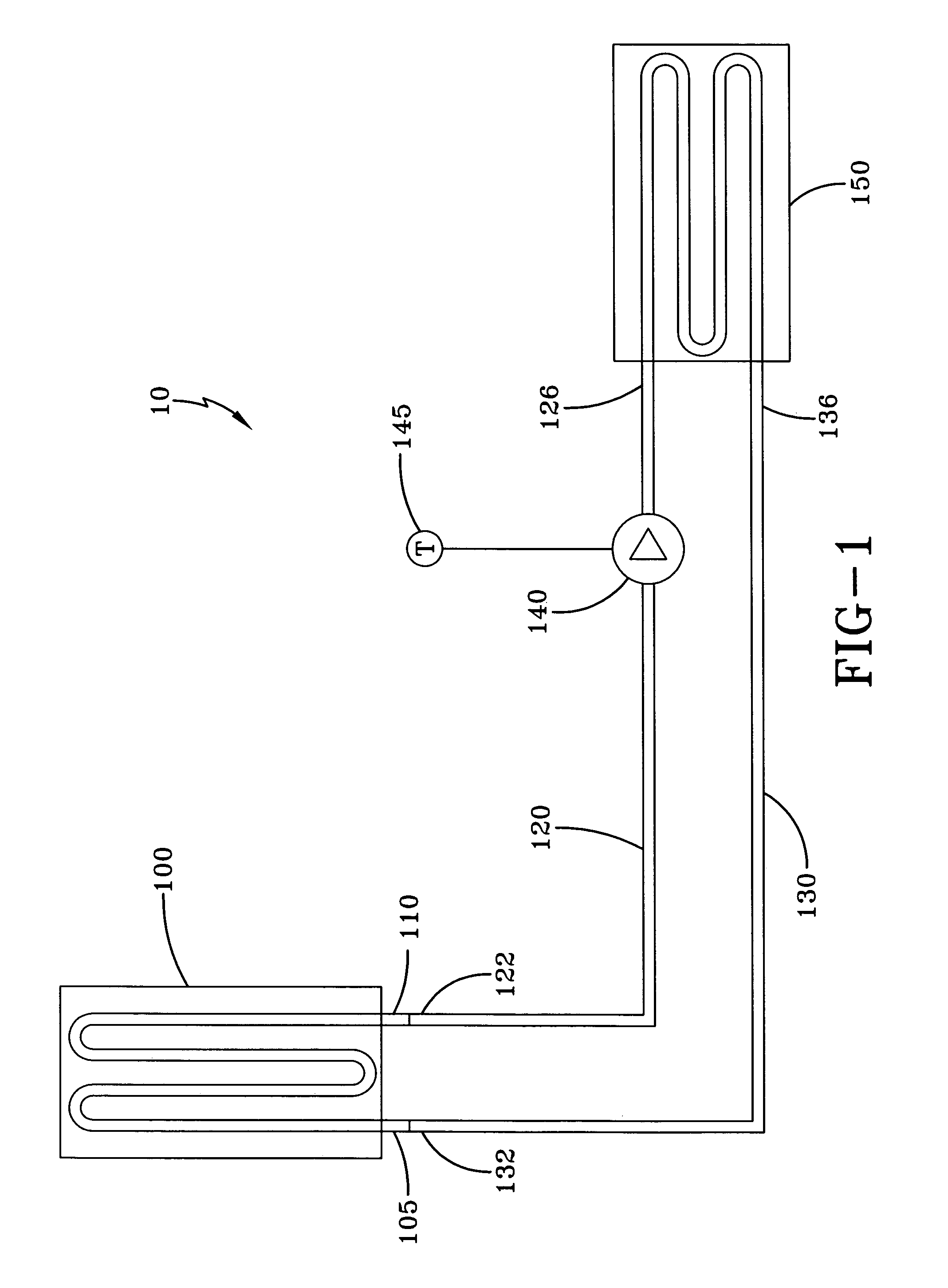
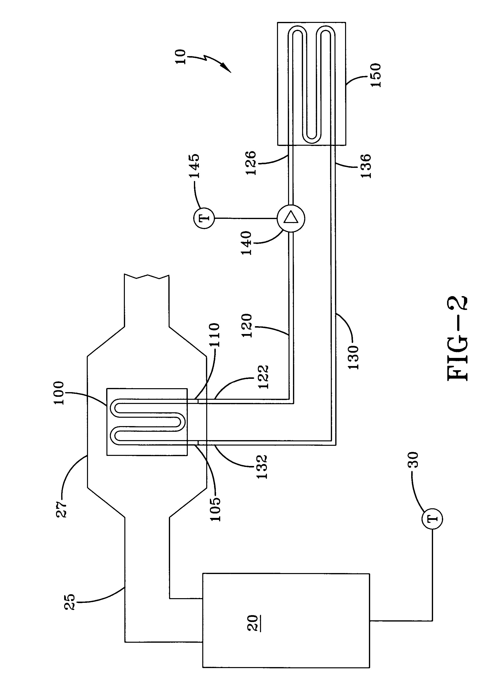
[0016]FIG. 1 is a schematic illustration of an apparatus 10 that is an embodiment of the present invention. The apparatus 10 comprises: an air-to-fluid heat exchanger 100; a fluid supply conduit 120; a fluid return conduit 130; a pump 140; a secondary thermostat 145; and a radiant heating loop 150. FIG. 2 illustrates the apparatus 10 installed in conjunction with a forced air furnace 20 connected to a hot air duct 25.

[0017]Referring to FIG. 2, the forced air furnace 20 can be any forced air furnace as commonly known by those skilled in the art, such as for example a gas furnace, oil furnace or heat pump. The forced air furnace 20 will typically be the primary source of heating for the building and will be connected to the hot air duct 25. The hot air duct 25 is operative to distribute an air flow that is heated by the forced air furnace 20 throughout the building. The forced air furnace 20 will typically be controlled with a furnace thermostat 30 that is located in the main occupied...


PUM


Abstract

A radiant heating system includes an air-to-fluid heat exchanger, a radiant heating loop and a pump and conduits to circulate heating fluid between the air-to-fluid heat exchanger and the radiant fluid loop. The air-to-fluid heat exchanger is installed within a hot air duct connected to a conventional forced air furnace; preferably in a section of the hot air duct located near the forced air furnace with an expanded cross-section. In operation, the apparatus uses heated air supplied by the forced air furnace to heat the heating fluid circulating through the apparatus. Some of the heat from an air flow supplied by the forced air furnace passing through the hot air duct is transferred to heating fluid in the air-to-fluid heat exchanger, installed within the hot air duct. This heating fluid is then circulated through a radiant heating loop to heat a desired area.

Description

[0001]This invention is in the field of heating systems and more particular relates to a radiant heating system using heating fluid.BACKGROUND[0002]Many buildings heating systems, especially residential buildings heating systems, use a primary heating system which comprises a forced air furnace for heating and cooling. Air is heated by the forced air furnace and dispersed throughout the building through ducting. While there are many advantages and reasons for using a forced air furnace as the primary heating system in a building, there are some applications where it is desirable to have in addition to the forced air heating, a radiant heating system using circulating heating fluid for specialized heating, that cannot be achieved with a forced air furnace alone.[0003]Additionally, using forced air heating alone often involves some disadvantages. A common disadvantage of using a forced air furnace alone is that the heated air in a room, because it has a tendency to rise, can often lea...

Claims


Application Information

Patent Timeline
Patent Type & Authority Patents(United States)
IPC IPC(8): F24D5/10F23C3/00F24D3/02F24D3/12F24D5/02F24D9/00F24H3/12F28D21/00
CPCF24D3/12F28D21/0007F24D9/00Y02B30/00
Inventor MACPHERSON, MURDOCH
Owner MACPHERSON ENG
Learn More