
Floor heating and air conditioning integrated device based on air source heat pump technology

An air source heat pump, air conditioning technology, applied in air conditioning systems, space heating and ventilation, hot water central heating systems, etc., can solve the problems of high cost, troublesome installation and operation, many internal components, etc., to achieve ultra-high cost performance , the effect of convenient control and simple structure

Active Publication Date: 2014-07-09
KOCHEM ELECTRICAL
View PDF10 Cites 10 Cited by
  • Summary
  • Abstract
  • Description
  • Claims
  • Application Information

AI Technical Summary

Problems solved by technology

With the restricted use of non-renewable energy such as coal, oil, and gas as primary energy sources, and factors such as electric heating and energy consumption, these products are facing the situation of being eliminated; with the development of air source heat pump technology, air source heat pumps are used for refrigeration, Heating is gradually accepted by the public, but if several separate devices are used for heating and cooling, a lot of equipment will be invested, and there are many disadvantages such as high investment cost, large floor area, high energy consumption, troublesome installation and operation; there are also some Air source heat pump triple supply units are used in large spaces, that is, air conditioners, floor heating, and hot water all-in-one units. However, there are many internal components, complex structures, large volumes, and high costs. They are not suitable for use in homes or small spaces, and heating must be performed at the same time in winter. Water, low energy efficiency ratio, slow heating, cooling and heating cannot be automatically adjusted

Method used


Image

  • Floor heating and air conditioning integrated device based on air source heat pump technology

Examples


Embodiment Construction

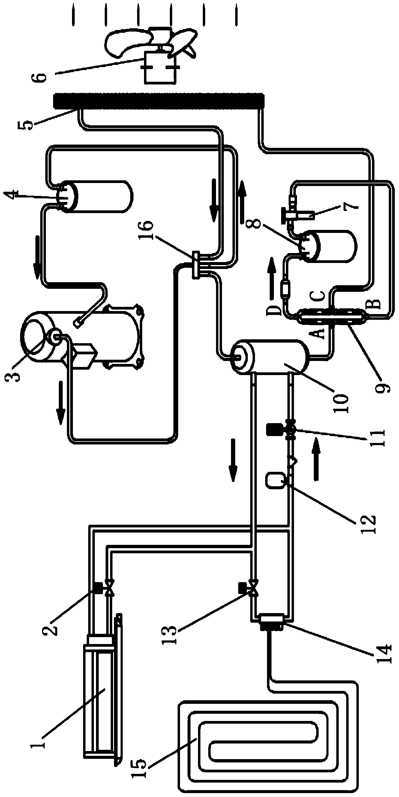
[0021] see figure 1 , an integrated floor heating and air conditioning device based on air source heat pump technology, which includes a fan coil unit 1, a fan coil solenoid valve 2, a compressor 3, a gas-liquid separator 4, an evaporator 5, an expansion valve 7, and a liquid reservoir 8. One-way valve bridge device 9, condenser 10, circulation pump 11, expansion tank 12, floor heating solenoid valve 13, water separator 14, floor heating pipeline 15, four-way valve 16;

[0022] The output port of the condenser 10 is connected to the input port of the condenser 10 through the floor heating solenoid valve 13, the water separator 14, the expansion tank 12, and the circulation pump 11 in sequence; The valve 2 is connected to the output port of the condenser 10, and the other end of the fan coil 1 is connected between the water separator 14 and the expansion tank 12; the floor heating pipeline 15 is connected to the water separator 14 through a pipeline;

[0023] The output port o...


PUM


Abstract

The invention discloses a floor heating and air conditioning integrated device based on an air source heat pump technology. The floor heating and air conditioning integrated device comprises a compressor, a condenser, an evaporator, expansion valve and other assemblies. In the heating process, the compressor, a four-way valve, the condenser, a single-way valve bridge-type device (A-D), a liquid accumulator, the expansion valve, a single-way valve bridge-type device (B-C), the evaporator, a gas-liquid separator and the compressor are sequentially connected to form a circulation; in the refrigerating process, the compressor, the four-way valve, the evaporator, a single-way valve bridge-type device (C-D), the liquid accumulator, the expansion valve, a single-way valve bridge-type device (B-A), the condenser, the gas-liquid separator and the compressor are sequentially connected to form a circulation. The floor heating and air conditioning integrated device has the advantages of being suitable for installation spaces different in size, simple in structure, low in cost, small in size, convenient to control and the like.

Description

technical field [0001] The invention relates to an integrated device for floor heating and air conditioning based on air source heat pump technology. Background technique [0002] The main cooling and heating equipment for general households or small spaces is household split air conditioners, the cooling and heating equipment for large spaces is mainly central air conditioners, and the floor heating equipment is various boilers. With the restricted use of non-renewable energy such as coal, oil, and gas as primary energy sources, and factors such as electric heating and energy consumption, these products are facing the situation of being eliminated; with the development of air source heat pump technology, air source heat pumps are used for refrigeration, Heating is gradually accepted by the public, but if several separate devices are used for heating and cooling, a lot of equipment will be invested, and there are many disadvantages such as high investment cost, large floor a...

Claims


Application Information

Patent Timeline
IPC IPC(8): F25B13/00F25B29/00F25B41/04F24D3/18F24F5/00F25B41/20F25B41/31
Inventor 杜贤平杭文斌华青梅何航徐智升
Owner KOCHEM ELECTRICAL
Learn More