Swing arm type double-wheel-track composite special engineering vehicle chassis
An engineering vehicle, swing arm technology, applied to tracked vehicles, vehicle maintenance, vehicle parts, etc., can solve the problems of slow movement, inability to bear loads, tire-type mechanical vehicles that cannot meet the requirements of driving on bad roads, etc., to increase adaptability capacity, increased adaptability and the effect of operating speed
- Summary
- Abstract
- Description
- Claims
- Application Information
AI Technical Summary
Problems solved by technology
Method used
Image

Examples
Embodiment Construction
[0028] Describe the present invention below in conjunction with specific embodiment:
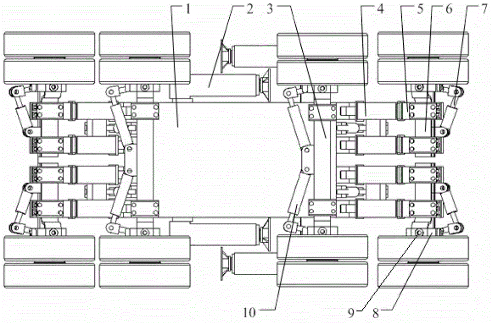
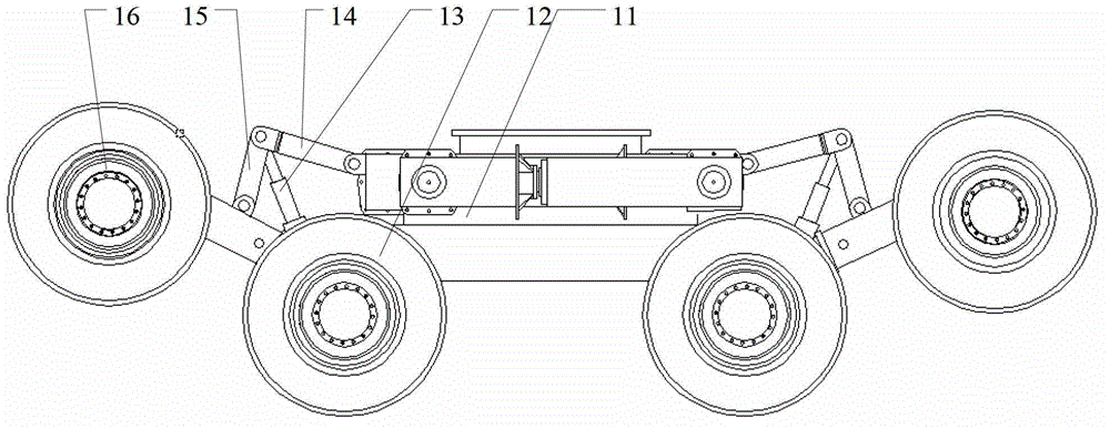
[0029] Refer to attached figure 1 , the swing-arm type double-section wheel-track composite special engineering vehicle chassis in this embodiment includes a vehicle frame 1, a main bridge assembly, a half-bridge assembly and outrigger assemblies. The overall structure is front-to-back and left-right symmetrical.
[0030] The main axle assembly includes a main axle 3 , main wheels 12 and a main axle steering oil cylinder 10 . The main axle is divided into front and rear two main axles, which are symmetrically fixed at the bottom of the frame; both ends of the main axle are respectively connected to the main wheels through their own rotating brackets 8, and each main wheel is connected by its own hydraulic motor. 9 independent drives. The end of the steering cylinder body of the main axle is hingedly connected with the middle part of the main axle, and the output end of the steering cylind...
PUM
 Abstract
Description
Claims
Application Information
 - R&D
- Intellectual Property
- Life Sciences
- Materials
- Tech Scout
- Unparalleled Data Quality
- Higher Quality Content
- 60% Fewer Hallucinations
Browse by: Latest US Patents, China's latest patents, Technical Efficacy Thesaurus, Application Domain, Technology Topic, Popular Technical Reports.
© 2025 PatSnap. All rights reserved.Legal|Privacy policy|Modern Slavery Act Transparency Statement|Sitemap|About US| Contact US: help@patsnap.com