Compact range antenna measuring system

An antenna measurement and field compression technology, applied in the antenna radiation pattern, electromagnetic field characteristics and other directions, can solve the problems of high processing requirements and high cost, and achieve the effect of reducing the cost of construction

Active Publication Date: 2012-10-24
KUANG CHI INST OF ADVANCED TECH +1
View PDF6 Cites 23 Cited by
  • Summary
  • Abstract
  • Description
  • Claims
  • Application Information

AI Technical Summary

Problems solved by technology

[0011] The invention provides a compact field antenna measurement system, which solves the problems of the existing compact field antenn

Method used


Image

  • Compact range antenna measuring system
  • Compact range antenna measuring system
  • Compact range antenna measuring system

Examples


Embodiment Construction

[0028] An embodiment of the present invention provides a compact field antenna measurement system, which will be described in detail below with reference to the accompanying drawings.

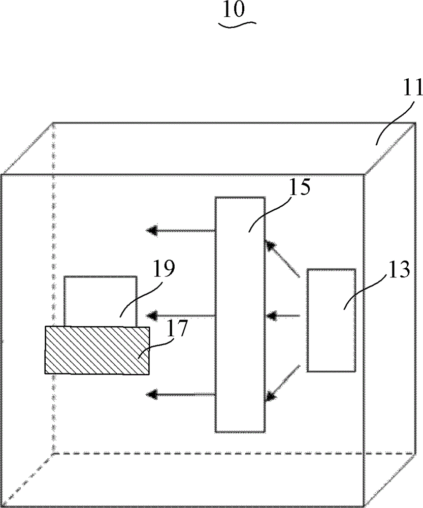
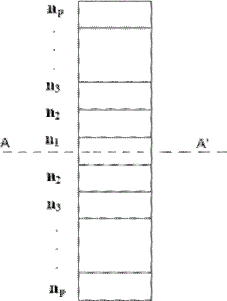
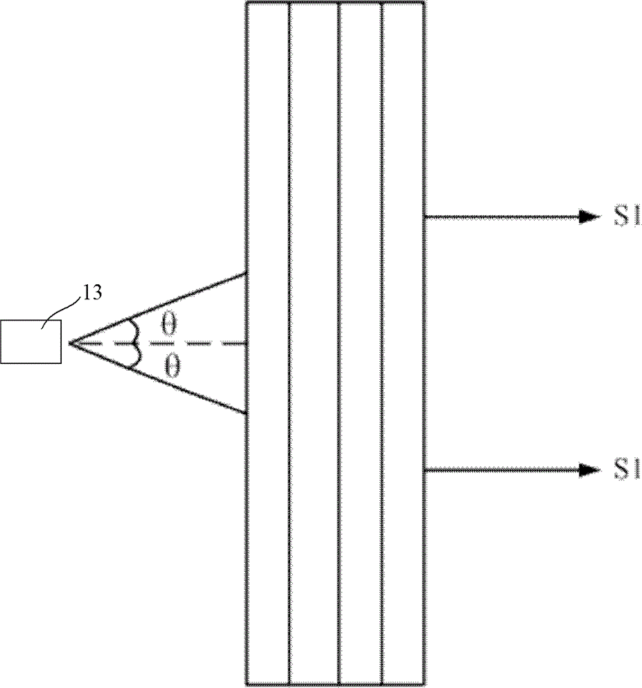
[0029] see figure 2 , a schematic diagram of the compact field antenna measurement system 10 generating planar electromagnetic waves. The compact field antenna measurement system 10 includes a microwave anechoic chamber 11 , a feed source 13 arranged in the microwave anechoic chamber 11 , an antenna test turntable 17 and a plane wave generating unit 15 , wherein the plane wave generating unit 15 is made of metamaterial. The feed 13 and the antenna test turntable 17 of the compact field antenna measurement system 10 are respectively located on two sides of the plane wave generating unit 15 . After the electromagnetic wave generated by the feed source 13 is refracted by the plane wave generating unit 15 , a quasi-plane wave test area with excellent performance is provided on the antenna test tu...


PUM


Abstract

The invention discloses a compact range antenna measuring system which comprises a feed source which is arranged in a microwave anechoic chamber and a planar wave generation unit formed by a plurality of meta-material layers which are overlapped with one another, wherein each meta-material layer comprises a substrate and a plurality of artificial hole micro-structures on the substrate; and electromagnetic waves generated by the feed source are converted into planar electromagnetic waves after passing through the planar wave generation unit. A reflecting surface in the prior art is replaced by the planar wave generation unit made from meta-materials, and the refraction characteristics of the planar wave generation unit are simulated by a computer according to test requirements, so that an antenna testing turntable is provided with a quasi-plane-wave testing area with excellent performance after the electromagnetic waves generated by the feed source are refracted by the planar wave generation unit. Thereby, the manufacturing of a high-precision reflecting surface and a high-difficulty processing technique are omitted, and thus the manufacturing cost of the compact range antenna measuring system is greatly reduced.

Description

【Technical field】 [0001] The invention relates to the field of compact field testing, in particular to a compact field antenna measurement system containing metamaterials. 【Background technique】 [0002] At present, the basic methods for measuring the scattering characteristics of targets (such as antennas, etc.) include far-field method, compact field method and near-field method. For the far-field method, let D be the maximum cross-sectional size of the target to be measured, and r be the distance between the transmitting antenna and the target to be measured, then when r≥2D^2 / λ (λ is the wavelength), it can be approximately considered as projected to the target The electromagnetic waves on the target are planar electromagnetic waves. Similarly, the distance between the receiving antenna and the target to be measured should also meet this requirement, so that the receiving antenna can receive the scattered far field. By rotating the target to be measured and measuring th...

Claims


Application Information

Patent Timeline
IPC IPC(8): G01R29/08G01R29/10
Inventor 刘若鹏徐冠雄张洋洋赵治亚
Owner KUANG CHI INST OF ADVANCED TECH
Why Eureka
Try Eureka