Low-cost broadband vertical polarization ultra high frequency (UHF) wave band antenna installed in limited space

A technology with limited space and vertical polarization, applied in the direction of the connection of the antenna grounding switch structure, the structure of the radiating element, etc., it can solve the problems of narrow operating frequency band, difficult to achieve effect, large antenna installation size, etc. Effect

Inactive Publication Date: 2014-04-16
NORTHWESTERN POLYTECHNICAL UNIV
View PDF2 Cites 0 Cited by
  • Summary
  • Abstract
  • Description
  • Claims
  • Application Information

AI Technical Summary

Problems solved by technology

The "J" type dipole antenna has the characteristics of simple structure and easy tuning, but it often has a narrow operating frequency band (less than 5%). Generally, it works at a point frequency, and it is difficult to achieve the effect through ordinary measures to increase bandwidth. Especially in the UHF frequency band, it cannot meet the requirements of broadband communication
Another kind of disc-cone antenna consists of a conductor disc and a conductor cone. The diameter of the antenna disc and the height of the cone are approximately one-half of the wavelength. Therefore, the overall installation size of the antenna is too large when working in a lower frequency band. It is difficult to meet the requirements of miniaturization and portability on mobile platforms
Ordinary dipole antennas, no matter in the form of a sleeve or a reflective ground grid, have a large physical installation size when working in the UHF frequency band. Brown G.H. and O.M.Woodward (Brown G.H., O.M.Woodward, Experimentally Determined Radiation Characteristics of Conical and Triangular Antennas [J], RCA Review, Vol.13, December 1952, PP.425-452.) proposed a "butterfly" type ultra-wideband dipole antenna, but the antenna can not meet the common 50 Ohm's RF coaxial cables directly match the needs of interconnect

Method used


Image

  • Low-cost broadband vertical polarization ultra high frequency (UHF) wave band antenna installed in limited space
  • Low-cost broadband vertical polarization ultra high frequency (UHF) wave band antenna installed in limited space
  • Low-cost broadband vertical polarization ultra high frequency (UHF) wave band antenna installed in limited space

Examples


Embodiment Construction

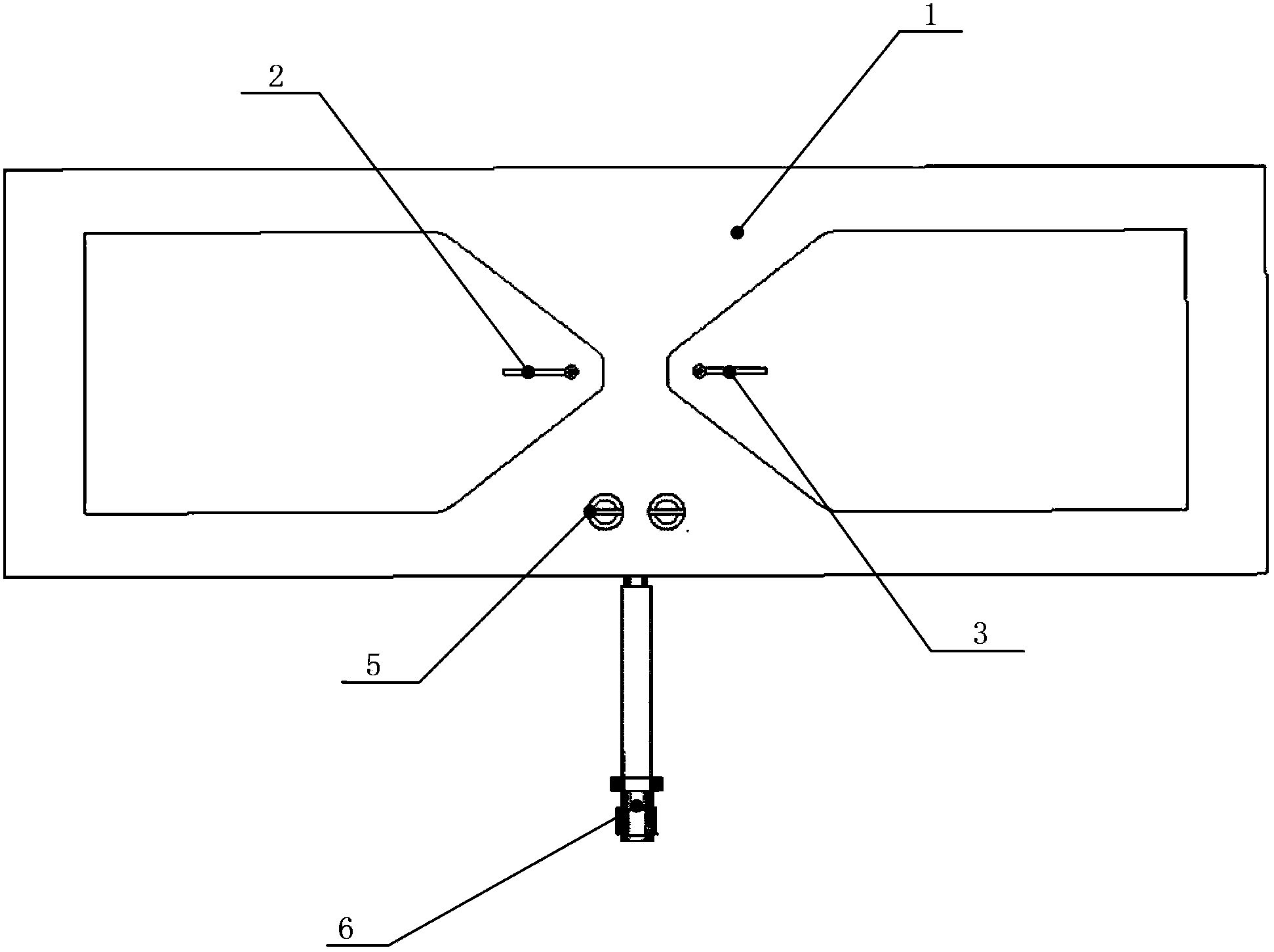
[0018] The technical solution adopted by the present invention to solve the technical problem is: comprising an antenna element, a forward direct connection cable, a reverse balanced connection cable, a cable fixing clip and a radio frequency connector. The antenna element is made of ordinary FR-4 single-sided copper-clad PCB board, and the antenna radiation body is formed by etching the copper-clad surface. The antenna radiation element is composed of two sections with left and right mirror images. Each section is also divided into upper and lower parts, and the total height of the two parts is a quarter of a wavelength. The upper part is formed from the top of the single-section array to two-thirds of the total height of the single-section array, and its overall shape is rectangular, with a width of one-eighth of the wavelength. The lower part of the single-section array is formed from 2 / 3rds of the total height of the single-section array to the bottom of the single-section...


PUM


Abstract

The invention discloses a low-cost broadband vertical polarization ultra high frequency (UHF) wave band antenna installed in a limited space. The low-cost broadband vertical polarization UHF wave band antenna comprises an antenna oscillator, a forward direct-connection connecting cable, a reverse balance connecting line, a cable fixing clamp and a radio frequency connecting piece. An antenna radiation oscillator body is manufactured by processing common single-face printed circuit board (PCB) copper-clad plate, an antenna and a feeding port of a 50-ohm radio frequency cable are designed by adopting a forward and reverse balance feed principle, and the requirements for simple direct connection and broadband work of the antenna and the 50-ohm radio frequency cable within a UHF wave band are met by optimizing an antenna oscillator structure and the size of the feeding port.

Description

technical field [0001] The invention relates to a broadband UHF band antenna. Background technique [0002] At present, the UHF band communication lines on commonly used portable mobile platforms are mostly "J"-shaped dipole, disc cone or dipole antennas. The "J" type dipole antenna uses the three-quarter wavelength main element as the basic radiation unit of the antenna, and introduces a quarter-wavelength matching element structure next to the main element to complete the matching between the overall system and the 50-ohm feed. According to the ordinary dipole matching mode, W.B. Freely first proposed the design of the antenna in the article "A Two meter J Antenna" (W.B. Freely, A Two meter J Antenna [J] QS T, April, 1977). The "J" type dipole antenna has the characteristics of simple structure and easy tuning, but it often has a narrow operating frequency band (less than 5%). Generally, it works at a point frequency, and it is difficult to achieve the effect by ordinary ...

Claims


Application Information

Patent Timeline
Patent Type & Authority Patents(China)
IPC IPC(8): H01Q1/38H01Q1/50
Inventor 张朋刘春阳袁俊
Owner NORTHWESTERN POLYTECHNICAL UNIV
Why Eureka
Try Eureka