Fixed-frequency beam scanning antenna based on composite right/left hand transmission line and implementation method of fixed-frequency beam scanning antenna

A combined left-handed and beam-scanning technology, which is applied to antennas, antennas, antenna arrays, etc. on movable objects, can solve problems such as increasing the complexity of bias circuit design, and achieve large bandwidth, large scanning range, and bias The effect of simple circuit structure

Active Publication Date: 2022-05-17
PEKING UNIV
View PDF7 Cites 0 Cited by
  • Summary
  • Abstract
  • Description
  • Claims
  • Application Information

AI Technical Summary

Problems solved by technology

[0004] such as As shown in Figure 1, the equivalent circuit model of the existing composite left-handed transmission line includes two series capacitors CLH, two series inductors LRH, two A parallel capacitor CRH and two parallel inductors LLH form a symmetrical circuit on the left and right sides, and one side of the circuit is a series capacitor CLH It is connected in series with the series inductor LRH and then connected to the parallel parallel capacitor CRH and one end of the parallel inductor LLH. The equivalent circuit model has The two resonant angular frequencies are the resonant frequency of the left-hand part and the resonant angular frequency of the right-hand part; in the existing composite left-handed transmission line technology, in order to achieve a wide range of forward and backward beam scanning, it is necessary to change the parallel capacitance C at the same time A variable in RH and parallel inductance LLH, and a variable in series capacitance CLH and series inductance LRH , to change the resonant frequency of the left-hand part and the resonant angular frequency of the right-hand part at the same time. Changing the above two variables at the same time generally requires two independent control voltages. This technique increases the complexity of the bias circuit design.

Method used


Image

  • Fixed-frequency beam scanning antenna based on composite right/left hand transmission line and implementation method of fixed-frequency beam scanning antenna
  • Fixed-frequency beam scanning antenna based on composite right/left hand transmission line and implementation method of fixed-frequency beam scanning antenna
  • Fixed-frequency beam scanning antenna based on composite right/left hand transmission line and implementation method of fixed-frequency beam scanning antenna

Examples


Embodiment Construction

[0048] The present invention will be further elaborated below through specific embodiments in conjunction with the accompanying drawings.

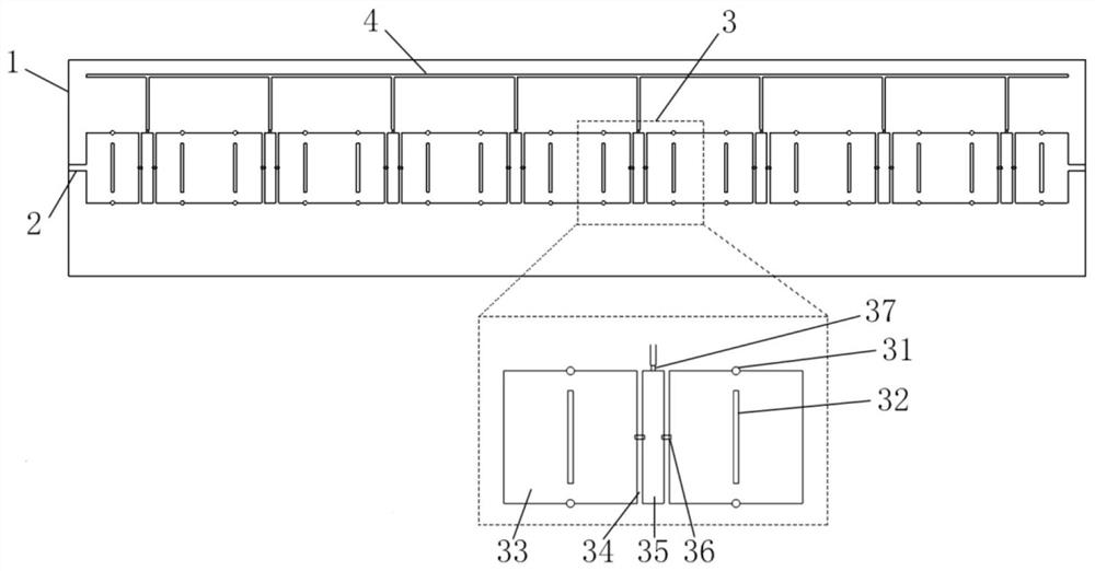
[0049] like figure 2 As shown, the fixed-frequency beam scanning antenna based on the composite left-handed transmission line of this embodiment includes: a dielectric substrate 1, an antenna unit 3, a microstrip line 2 and a DC bias line 4; wherein, a plurality of antenna units are formed on the dielectric substrate 1 3. A plurality of antenna units are arranged along one dimension to form an antenna array, and the arrangement direction of the antenna array is defined as the horizontal direction, and the direction perpendicular to the antenna array is the longitudinal direction; the two ends of the antenna array are respectively connected to the microstrip line 2 and the microstrip line 2 Connect to the RF connector, the RF connector at one end is connected to the microwave energy source as the feeding end of the microwave energy, and th...


PUM


Abstract

The invention discloses a fixed-frequency beam scanning antenna based on a composite right/left-handed transmission line and an implementation method of the fixed-frequency beam scanning antenna. In an equivalent circuit model of an antenna unit, a series capacitor CLH and a series inductor LRH on the left side and the right side are connected in series and then connected to one end of a parallel capacitor CRH and one end of a parallel inductor LLH which are connected in parallel, and a variable capacitor CV is connected in series between circuits on the two sides and then connected in parallel with a middle capacitor C; the variable capacitor CV and the middle capacitor C jointly change the resonance angular frequency of the left hand part and the resonance angular frequency of the right hand part, the capacitance value of the variable capacitance diode and the variable capacitor CV are controlled by using an external voltage source, and then the propagation constant beta is controlled, so that the radiation direction of the fixed-frequency beam scanning antenna is adjusted, and the radiation direction of the fixed-frequency beam scanning antenna is adjusted. According to the invention, a single variable is adjusted only by controlling the bias voltage to realize beam scanning; the fixed-frequency beam scanning antenna has the advantages of being simple in biasing circuit structure, large in scanning range, large in bandwidth and the like, and has good prospects in communication scenes such as mobile communication and satellite communication.

Description

technical field [0001] The invention relates to a fixed-frequency beam scanning antenna, in particular to a fixed-frequency beam scanning antenna based on a composite left and right-handed transmission line and a realization method thereof. Background technique [0002] Composite left and right handed transmission line antenna is a kind of leaky wave antenna with wide working bandwidth, high directivity, simple structure, advantages of low profile and frequency scanning characteristics. The beam angle radiated by the composite left-handed transmission line antenna will change with the operating frequency of the antenna, which increases the coverage area of ​​the antenna radiation beam. However, this frequency scanning feature is often not practical in actual communication scenarios. In communication, satellite communication and other scenarios that require beam scanning, the communication signal is a narrow-band signal with a fixed center frequency, so the fixed-frequency be...

Claims


Application Information

Patent Timeline
Patent Type & Authority Applications(China)
IPC IPC(8): H01Q1/38H01Q1/50H01Q1/24H01Q1/28H01Q13/08H01Q21/00
CPCH01Q1/38H01Q1/50H01Q1/241H01Q1/288H01Q21/0006H01Q13/08
Inventor 王艺东谭云华赵瑾张崇奇杜朝海刘濮鲲
Owner PEKING UNIV
Why Eureka
Try Eureka