Matrix group coding method of analog electronic circuit
A technology for simulating electronics and encoding methods, which is applied in the field of analog electronic circuit encoding, and can solve the problems of complex mapping process and low efficiency of circuit encoding and decoding.
- Summary
- Abstract
- Description
- Claims
- Application Information
AI Technical Summary
Problems solved by technology
Method used
Image
Examples
Embodiment 1
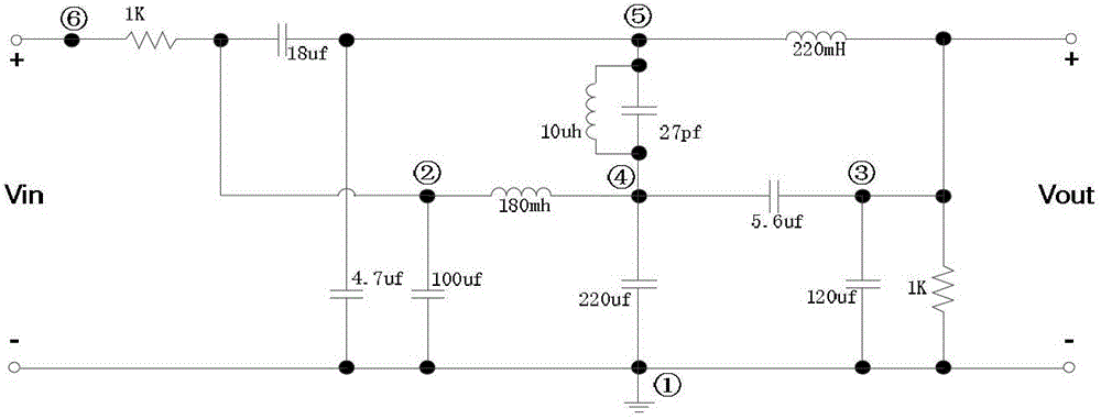
[0083] A "matrix group" encoding method for analog electronic circuits. The encoding method is as figure 1 As shown, it is composed of the "matrix group" code of the analog electronic circuit and the circuit operator, wherein: the "matrix group" code of the analog electronic circuit is "topological structure matrix" T, "first parameter matrix" S s and the "second parameter matrix" S o Collectively, the circuit operator is composed of two types: "operating operator" and "special operator".
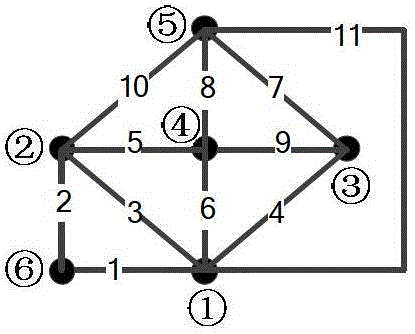
[0084] The analog electronic circuit as figure 2 As shown, it consists of resistors, inductors, capacitors and independent voltage sources; image 3 is an undirected single graph, and is also figure 2 Topology diagram of part of the circuit shown consisting of resistors, inductors, capacitors and independent voltage sources. figure 2 The number of the middle node and the image 3 The numbers of the corresponding nodes in are the same. exist figure 2 In , the circuit structure co...
Embodiment 2
[0150] A "matrix group" encoding method for analog electronic circuits. The encoding method is as follows figure 1 As shown, it is composed of the "matrix group" code of the analog electronic circuit and the circuit operator, wherein: the "matrix group" code of the analog electronic circuit is "topological structure matrix" T, "first parameter matrix" S s and the "second parameter matrix" S o Collectively, the circuit operator is composed of two types: "operating operator" and "special operator".
[0151] The analog electronic circuit as Image 6 As shown, it is composed of resistors, inductors, capacitors, independent voltage sources and BJT tubes, Figure 7 is an undirected single graph, and is also Image 6 Topology diagram of part of the circuit shown consisting of resistors, inductors, capacitors and independent voltage sources. Image 6 The number of the middle node and the Figure 7 The numbers of the corresponding nodes in are the same. exist Image 6 In , the ...
PUM
 Abstract
Description
Claims
Application Information
 - R&D
- Intellectual Property
- Life Sciences
- Materials
- Tech Scout
- Unparalleled Data Quality
- Higher Quality Content
- 60% Fewer Hallucinations
Browse by: Latest US Patents, China's latest patents, Technical Efficacy Thesaurus, Application Domain, Technology Topic, Popular Technical Reports.
© 2025 PatSnap. All rights reserved.Legal|Privacy policy|Modern Slavery Act Transparency Statement|Sitemap|About US| Contact US: help@patsnap.com


