
Plasma display panel and green phosphor layer

A green fluorescent and display panel technology, which is applied in the direction of AC plasma display panels, fluorescent layers, luminescent materials, etc., can solve problems such as poor color purity, reduced brightness, and shortened afterglow time of green phosphors

Inactive Publication Date: 2012-10-24
PANASONIC CORP
View PDF3 Cites 0 Cited by
  • Summary
  • Abstract
  • Description
  • Claims
  • Application Information

AI Technical Summary

Problems solved by technology

[0008] However, in the above-mentioned conventional method, although the afterglow time of the green phosphor can be shortened, the brightness decreases.
In addition, with Zn 2 SiO 4 :Mn or (Y,Gd)Al 3 B 4 o 12 : Tb compared to Y 3 Al 5 o 12 : The color purity of Ce is poor, so the color purity needs to be improved

Method used


Image

  • Plasma display panel and green phosphor layer
  • Plasma display panel and green phosphor layer
  • Plasma display panel and green phosphor layer

Examples


Embodiment Construction

[0028] Hereinafter, embodiments of the present invention will be described in detail.

[0029]

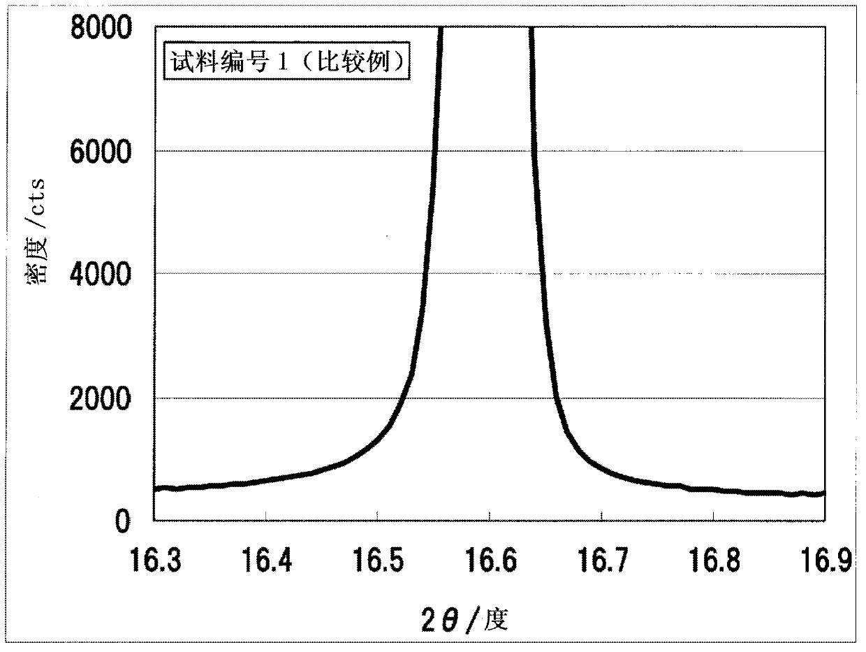
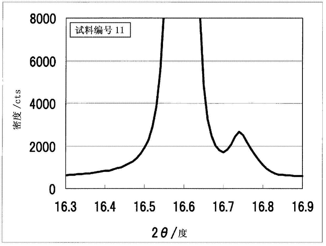
[0030] The first phosphor used in the present invention is represented by the general formula aYO 3 / 2 ·(3-a)CeO 3 / 2 · bAlO 3 / 2 ·cGaO 3 / 2 (2.80≤a≤2.99, 1.00≤b≤5.00, 0≤c≤4.00, where 4.00≤b+c≤5.00) means. Regarding a, a preferable range is 2.97≦a≦2.99 from the viewpoint of brightness. The first phosphor is characterized by the wavelength In the X-ray diffraction pattern measured by X-rays, there is a peak in the range where the diffraction angle 2θ is not less than 16.7 degrees and not more than 16.9 degrees.

[0031] The present inventors have found through detailed examination based on experimental results that a phosphor having high luminance and color purity can be obtained from a phosphor having the above-mentioned composition and conforming to the above-mentioned characteristics regarding the X-ray diffraction pattern. in the existing Y 3 al 5 o 12 : In the Ce phosph...


PUM

PropertyMeasurementUnit
thicknessaaaaaaaaaa
thicknessaaaaaaaaaa

Abstract

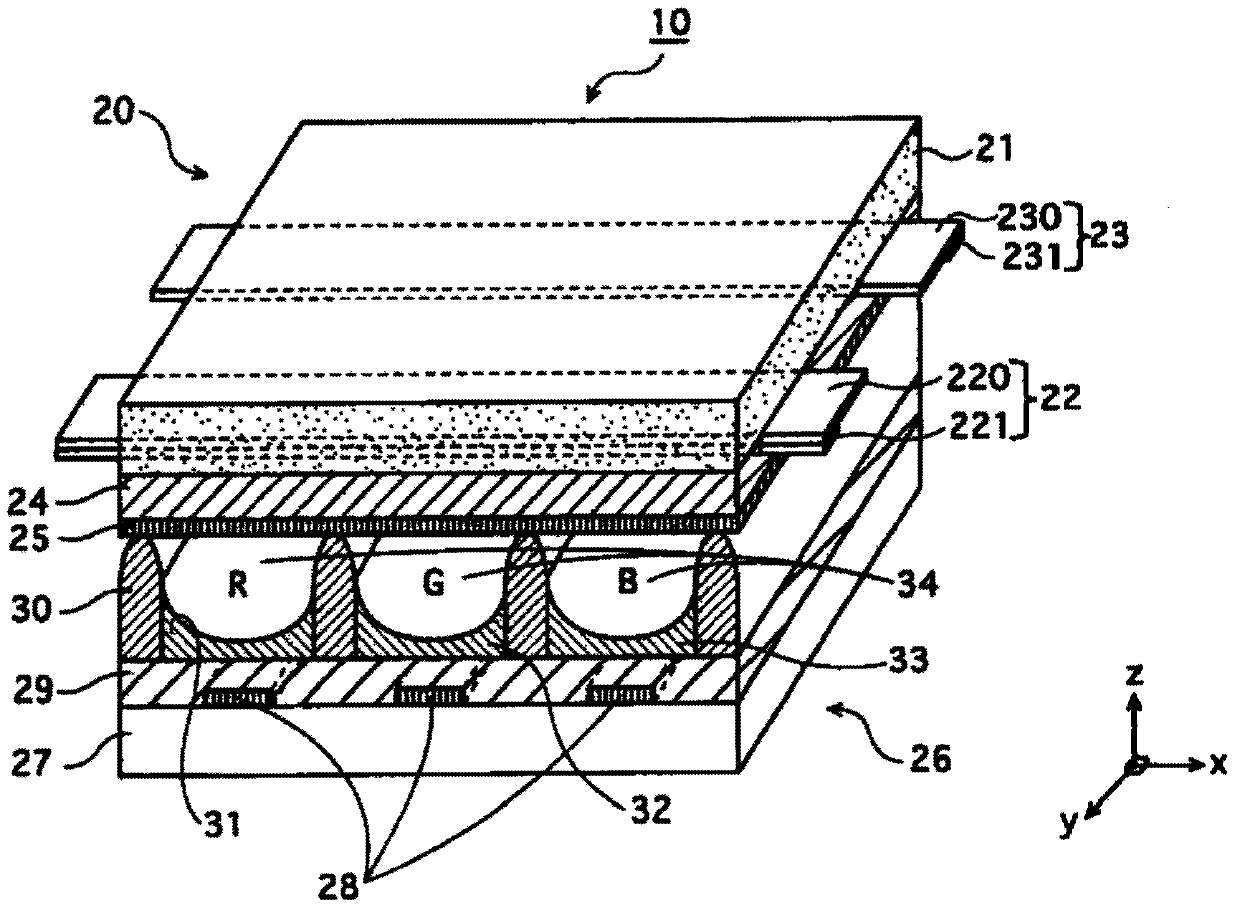
Disclosed is a highly efficient plasma display panel which has short afterglow time, while achieving high luminance and high color purity. Specifically disclosed is a plasma display panel comprising a green phosphor layer, which is characterized in that the green phosphor layer contains a phosphor that is represented by general formula: aYO3 / 2(3-a)CeO3 / 2bAlO3 / 2cGaO3 / 2 (wherein 2.80 <= a< = 2.99, 1.00 <= b <= 5.00 and 0< = c <= 4.00, provided that 4.00 <= b + c <= 5.00) and has a peak with a peak top at a diffraction angle (2-d) within the range from 16.7 DEG to 16.9 DEG (inclusive) in the X-ray diffraction pattern as determined by an X-ray having a wavelength of 0.774 AA. The plasma display panel is also characterized in that the green phosphor layer additionally contains a phosphor that is represented by general formula: dZnO(2-d)MnO.eSiO2 (wherein 1.80 <= d <= 1.90 and 1.00 <= e <= 1.02) in an amount of 30-80% by weight (inclusive) based on the total weight of the green phosphor.

Description

technical field [0001] The present invention relates to a plasma display panel (PDP) and a green phosphor layer. Background technique [0002] In recent years, various aluminate phosphors have been used as phosphors for PDPs. For example, BaMgAl is used as a blue phosphor 10 o 17 :Eu, (Y, Gd)Al is used as a green phosphor 3 B 4 o 12 :Tb and Zn 2 SiO 4 : Mixture of Mn. [0003] However, using Zn as a green phosphor 2 SiO 4 :Mn or Zn 2 SiO 4 : Mn and (Y, Gd) Al 3 B 4 o 12 In the case of a hybrid of :Tb, since the afterglow time is long, the animation characteristics as a PDP are not good. Therefore, green phosphors with a short afterglow time are strongly required for PDP applications. [0004] On the other hand, it is proposed to use Y with a significantly short afterglow time as a green phosphor. 3 al 5 o 12 : A method of Ce (for example, refer to Patent Document 1). [0005] 【Prior technical literature】 [0006] 【Patent Literature】 [0007] [Patent Doc...

Claims


Application Information

Patent Timeline
Patent Type & Authority Applications(China)
IPC IPC(8): H01J11/12C09K11/77C09K11/08C09K11/59C09K11/64C09K11/80H01J11/22H01J11/24H01J11/26H01J11/34H01J11/42
CPCH01J2211/42H01J11/12H01J11/42C09K11/7774C09K11/08
Inventor 奥山浩二郎
Owner PANASONIC CORP
Learn More