
Ice melting system for overhead contact system of electric railway

A technology for electrified railways and catenaries, applied in the direction of overhead lines, etc., can solve the problems of large device loss, complicated operation, inability to realize online control and dynamic switching, and achieve the effect of increasing force rate and real-time compensation of reactive power

Active Publication Date: 2015-05-13
ZHUZHOU NAT ENG RES CENT OF CONVERTERS
View PDF8 Cites 0 Cited by
  • Summary
  • Abstract
  • Description
  • Claims
  • Application Information

AI Technical Summary

Problems solved by technology

Theoretically speaking, this method of anti-icing technology is simple and effective, and Joule heat is generated by high current for anti-icing. However, this method has relatively large device loss during operation, and at the same time generates a large number of harmonics to the power supply system, which in turn leads to traction The power supply rate is too low, seriously affecting the quality of power supply, and it needs to be shut down and put into operation, the operation is complicated, and online control and dynamic switching cannot be realized

Method used


Image

  • Ice melting system for overhead contact system of electric railway
  • Ice melting system for overhead contact system of electric railway
  • Ice melting system for overhead contact system of electric railway

Examples


Embodiment Construction

[0022] In order to make the above objects, features and advantages of the present invention more comprehensible, the present invention will be further described in detail below in conjunction with the accompanying drawings and specific embodiments.

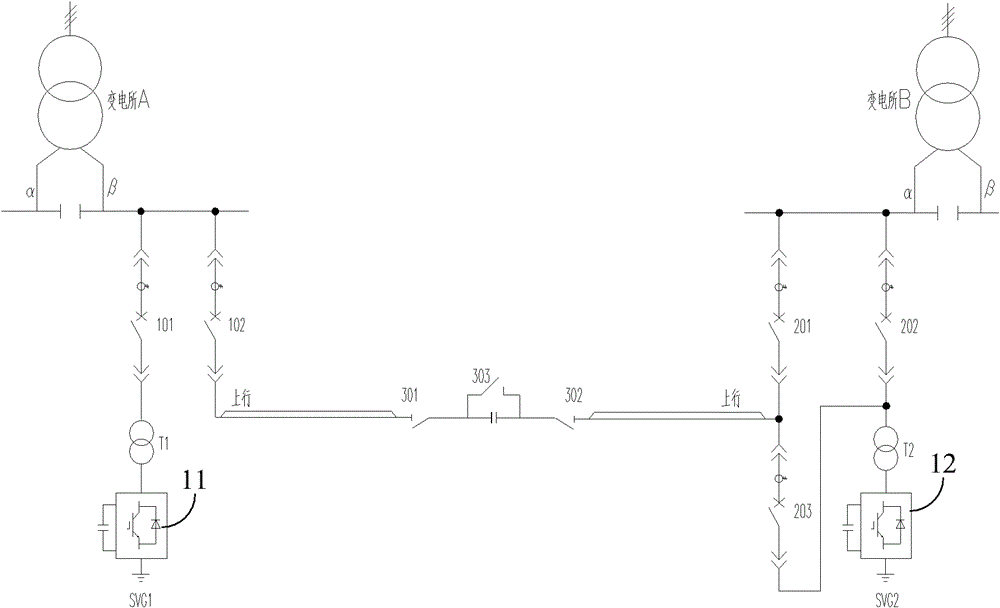
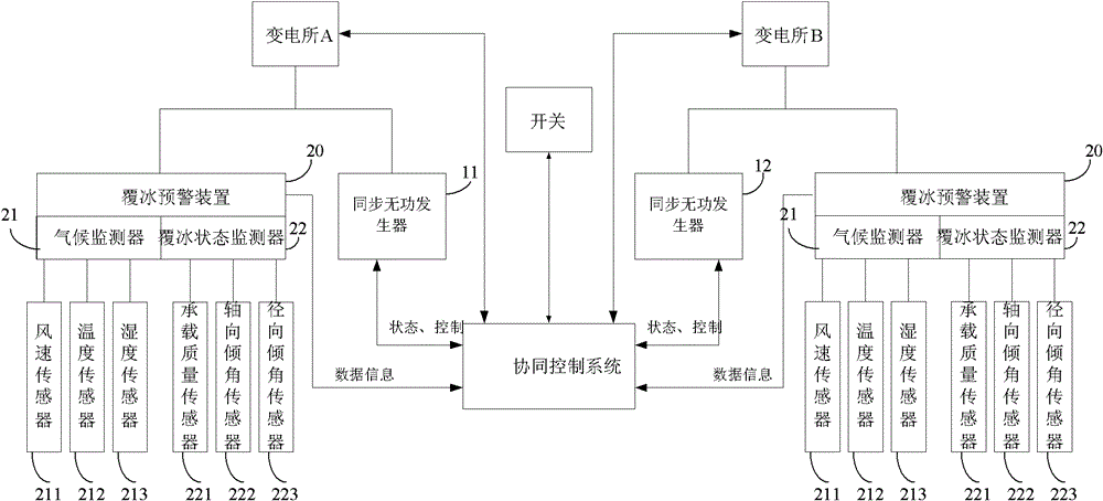
[0023] In the present invention, synchronous var generators (SVG) are respectively arranged on the adjacent power supply arms of the two substations of the contact network. The power generator generates an equal amount of capacitive reactive power-Q, so that reactive current flows from the power supply arm, generating Joule heat to achieve the effect of melting ice.

[0024] see figure 1 , showing the structure of the electrified railway catenary ice melting system. A synchronous var generator 11 and a synchronous var generator 12 are respectively installed on the β supply arm of the traction substation A and the α supply arm of the traction substation B. The synchronous var generator 11 is connected to the β power supply arm th...


PUM


Abstract

The invention relates to an ice melting system for an overhead contact system of an electric railway. A first synchronous reactive generator and a second synchronous reactive generator are respectively arranged on adjacent power supply arms of two electric power substations of the overhead contact system, wherein the first synchronous reactive generator is used for generating inductive reactive power during ice melting and transmitting the inductive reactive power to the overhead contact system; the second synchronous reactive generator is used for generating capacitive reactive power equivalent to the inductive reactive power during ice melting and transmitting the capacitive reactive power to the overhead contact system; and the second synchronous reactive generator is connected with the power supply arm of one electric power substation through a switch (203) and is also connected with the power supply arm of the other electric power substation through a second switch (202). According to the ice melting system disclosed by the invention, reactive current flows from the power supply arms to generate joule heat energy for melting ice. The influence on a last-stage traction power supply system by the reactive power generated by the ice melting system disclosed by the invention is avoided; when the ice melting is not required, the power of two synchronous reactive generators is supplied by respective electric power substations, and thus real-time compensation of reactive power is realized and the aim of increasing the power rate of a traction network is achieved.

Description

technical field [0001] The invention relates to the field of electric power system power supply, in particular to an ice-melting system for an electrified railway catenary. Background technique [0002] With the vigorous development of China's railway transportation, railways are playing an increasingly important role in national economic construction and national defense construction. Freight separation, double track rate and electrification rate are all over 50%. China Railway will form a grand blueprint of "four horizontal and four vertical" high-speed railway network. [0003] In recent years, affected by global warming, extreme weather and climate disasters have become more frequent. There have been rare ice and snow disasters in foreign countries and in southern, central and eastern China, especially in Hunan, Guizhou, Guangxi, Most areas in Jiangxi were seriously affected by the disaster, and the power facilities suffered unprecedented damage. The accidents of power ...

Claims


Application Information

Patent Timeline
Patent Type & Authority Patents(China)
IPC IPC(8): B60M1/28
Inventor 周方圆王卫安黄燕艳谭胜武周靖段世彦龙礼兰石二磊王才孝朱建波文韬邱文俊吴明水胡前刘彤何政军
Owner ZHUZHOU NAT ENG RES CENT OF CONVERTERS
Learn More