Structure and application method of punching air inlet channel shared by liquid cooling system and environmental control system of airplane

An environmental control system and air intake technology, applied in aircraft parts, transportation and packaging, air handling equipment, etc., can solve the problems of large ram air volume and large compensation loss of aircraft fuel, reduce the total amount of ram air, The effect of overall weight reduction and complexity reduction

Inactive Publication Date: 2012-10-31
XIAN AIRCRAFT DESIGN INST OF AVIATION IND OF CHINA
View PDF6 Cites 17 Cited by
  • Summary
  • Abstract
  • Description
  • Claims
  • Application Information

AI Technical Summary

Problems solved by technology

The disadvantage is that the liquid cooling system and the environmental control system set up a separate ram intake port to require a large amount of ram air, and at the same time, the fuel compensation loss to the aircraft is also relatively large

Method used


Image

  • Structure and application method of punching air inlet channel shared by liquid cooling system and environmental control system of airplane
  • Structure and application method of punching air inlet channel shared by liquid cooling system and environmental control system of airplane
  • Structure and application method of punching air inlet channel shared by liquid cooling system and environmental control system of airplane

Examples


Embodiment 1

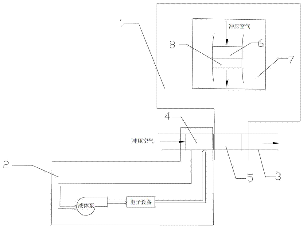
[0020] A structure in which an aircraft liquid cooling system and an environmental control system share a ram air intake is composed of a liquid cooling system 1, an environmental control system 2, and a ram air intake 3; the air-liquid heat exchanger 4 of the liquid cooling system 1 is installed in the The front of the secondary heat exchanger 5 of the control system 2. The primary heat exchanger 6 of the environmental control system 2 is installed in the engine nacelle 7, before the precooler 8; on this basis, the liquid cooling system 1 and the environmental control system 2 share the ram air intake 3, refer to the attached figure 1 , the air-liquid heat exchanger 4 of the liquid cooling system 1 and the secondary heat exchanger 5 of the environmental control system 2 share a ram air intake 3, and the ram air intake 3 is arranged on the top or bottom of the fuselage.

Embodiment 2

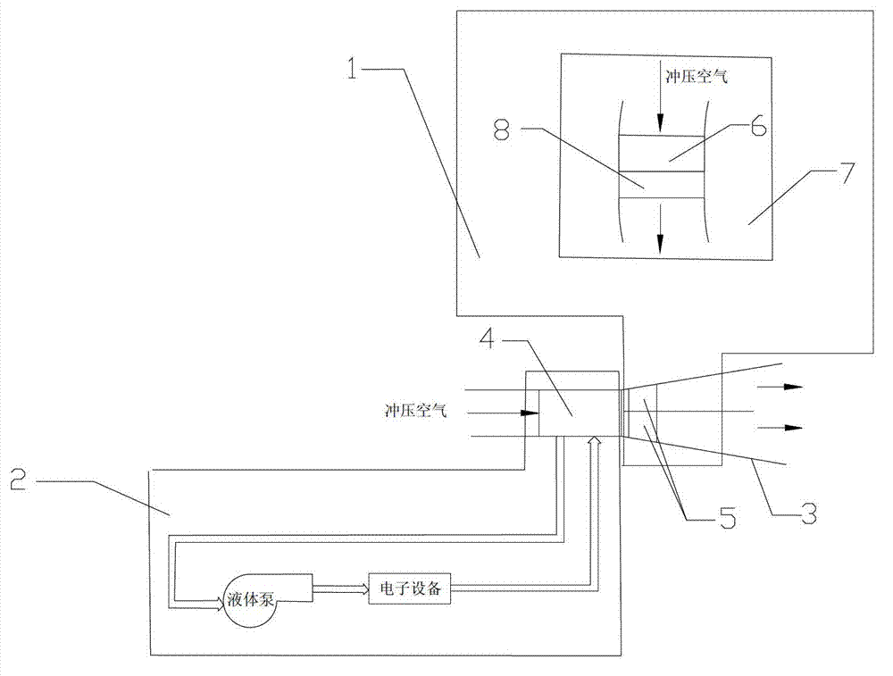
[0022] Reference attached figure 2 , on the basis of Embodiment 1, the air-liquid heat exchanger 4 of the liquid cooling system 1 and the secondary heat exchanger 5 of the environmental control system 2 share a ram air inlet 3, and the rear part of the ram air inlet 3 is divided into two The secondary heat exchangers 5 of the two environmental control systems are respectively installed in the two channels, and the ram air intake 3 is arranged on the top or bottom of the fuselage.

Embodiment 3

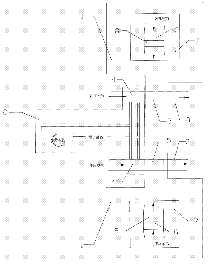
[0024] Reference attached figure 2 , on the basis of Embodiment 1, the air-liquid heat exchanger 4 of the liquid cooling system 1 and the secondary heat exchanger 5 of the environmental control system 2 share two ram air inlets 3, and the ram air inlets 3 are symmetrically arranged in on both sides of the fuselage.


PUM


Abstract

The invention relates to the field of airplane environment control, and is particularly applicable to comprehensive integrated design of a liquid cooling system and an environmental control system of an airplane. A structure of a punching air inlet channel shared by the liquid cooling system and the environmental control system of the airplane is formed by a liquid cooling system 1, an environmental control system 2 and a punching air inlet channel 3, wherein an air-liquid heat exchanger 4 of the liquid cooling system 1 is mounted at the front part of a secondary heat exchanger 5 of the environmental control system 2; a primary heat exchanger 6 of the environmental control system 2 is mounted in an engine nacelle 7 and in front of a pre-cooler 8; and the punching air inlet channel 3 is shared by the air-liquid heat exchanger 4 of the liquid cooling system 1 and the secondary heat exchanger 5 of the environmental control system 2. According to the structure disclosed by the invention, the total amount of punching air needed by the liquid cooling system and the environmental control system can be greatly reduced, so that the compensatory loss of fuel oil of the airplane is reduced, and endurance time is prolonged.

Description

technical field [0001] The invention relates to the field of aircraft environment control, and is especially suitable for the integrated design of an aircraft liquid cooling system and an environment control system. Background technique [0002] At present, most domestic and foreign aircraft environmental control systems adopt the structure of separate ram intakes for the liquid cooling system and the environmental control system, that is, the liquid cooling system and the environmental control system have their own separate ram intakes. The advantage of this structure is that the liquid cooling system and the environmental control system are equipped with separate ram air intakes, which has a simple structure and simple control logic. The disadvantage is that the liquid cooling system and the environmental control system need a large amount of ram air to set up a separate ram intake port, and at the same time, the fuel compensation loss to the aircraft is also relatively la...

Claims


Application Information

Patent Timeline
Patent Type & Authority Applications(China)
IPC IPC(8): B64D13/08
Inventor 齐社红马兰李荣军马庆林贾少鹏
Owner XIAN AIRCRAFT DESIGN INST OF AVIATION IND OF CHINA
Why Eureka
Try Eureka