Shear type expansion bolt
A technology of expansion bolts and bolts, applied in the direction of bolts, screws, nuts, etc., to achieve the effect of wide application environment, strong anchoring force, convenient and reliable use
- Summary
- Abstract
- Description
- Claims
- Application Information
AI Technical Summary
Problems solved by technology
Method used
Image
Examples
Embodiment 1
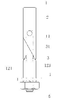
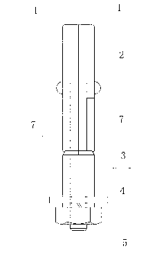
[0053] Such as figure 1 , 2 And shown in 3, the present invention comprises two expansion rods 1 that are semicircular in cross-section, and semicircular groove 6 and gap 7 are arranged on the expansion rod 1, and the upper end of expansion rod 1 is arc surface, and the bottom of expansion rod is provided with lower end slope 14 , the slope 14 at the lower end is facing inwardly; the two expansion rods 1 are hinged together with the upper end of the lug screw 5 through the riveting shaft 2, the hole on the upper end of the lug screw 5 is set on the riveting shaft 2, and 3 sets of wedges On the eared screw rod 5 and through the nut 4 screwed on one end of the screw rod 5, force is applied to push the lower end slopes of the two expansion rods 1 to make a scissors expansion movement, thereby achieving the purpose of anchoring or locking. The top end of the wedge 3 has a conical surface 31, and the taper of the conical surface 31 is consistent with the angle of the lower end slo...
Embodiment 2
[0055] Such as Figure 4 , 5 As shown in and 6, the present invention includes two expansion rods 1 with a semicircular cross section, and a lug nut support 8; the lower section of the expansion rod 1 is provided with a concave plane 9, so that the two expansion rods 1 are combined and embedded in Between the two opposite support plates 81 of the lug nut support 8 ; the concave plane 9 ends of the two expansion rods 1 are inserted on the lug nut support 8 , and hinged to it by the riveting shaft 2 . The upper end of the expansion rod 1 is an arc surface, and the lower part of the expansion rod is provided with a lower end slope 14, and the lower end slope 14 is facing inwardly; The inclined surface 14 at the lower end makes it perform a scissors-type stretching movement, and then achieves the purpose of anchoring or locking. Limiting steps 82 are provided on the outer sides of the roots of the two oppositely arranged support plates 81 on the lug nut bearing 8, and the slope ...
Embodiment 3
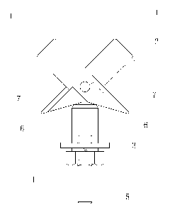
[0059] Such as Figure 7 , 8 As shown in and 9, this embodiment is basically the same as Embodiment 1, the difference is that the expansion rod 1 is replaced by an expansion plate 11, and there is no need to set semicircular grooves and gaps on the expansion plate 11. The present embodiment includes two expansion plates 11 whose both ends are sloped. The two expansion plates 11 lean against the two sides of the support plate of the lug screw 5 and are hinged by the riveting shaft 2. The wedges 3 are sleeved on the lugs. The screw rod 5 is given force by the nut 4, so as to push the slopes at the lower ends of the two expansion plates 11 to make them open in a scissor style, thereby achieving the purpose of anchoring or locking. If the eared screw 5 is set in the shape of double ears, two expansion plates 11 are embedded between the two ears (not shown).
PUM
 Abstract
Description
Claims
Application Information
 - R&D
- Intellectual Property
- Life Sciences
- Materials
- Tech Scout
- Unparalleled Data Quality
- Higher Quality Content
- 60% Fewer Hallucinations
Browse by: Latest US Patents, China's latest patents, Technical Efficacy Thesaurus, Application Domain, Technology Topic, Popular Technical Reports.
© 2025 PatSnap. All rights reserved.Legal|Privacy policy|Modern Slavery Act Transparency Statement|Sitemap|About US| Contact US: help@patsnap.com


