Dynamic hip joint prosthesis

A hip joint prosthesis, dynamic technology, applied in the direction of pivot connection, supporting machines, mechanical equipment, etc., can solve the problems that cannot be used for simulating joints, and achieve the effect of compact and reliable structure

Inactive Publication Date: 2012-10-31
AVIATION MEDICINE INST AIR FORCE PLA
View PDF3 Cites 10 Cited by
  • Summary
  • Abstract
  • Description
  • Claims
  • Application Information

AI Technical Summary

Problems solved by technology

[0003] At present, none of the simulation dummies in the prior art can be used to simulate the situation when the joints are subjected to extreme loads, especially w...

Method used


Image

  • Dynamic hip joint prosthesis
  • Dynamic hip joint prosthesis
  • Dynamic hip joint prosthesis

Examples


Embodiment Construction

[0020] The present invention will be described in further detail below in conjunction with the accompanying drawings and specific embodiments.

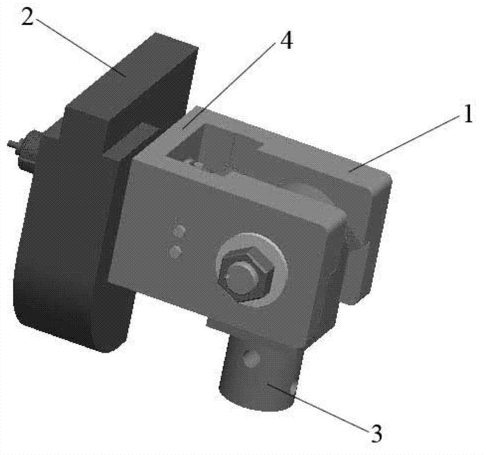
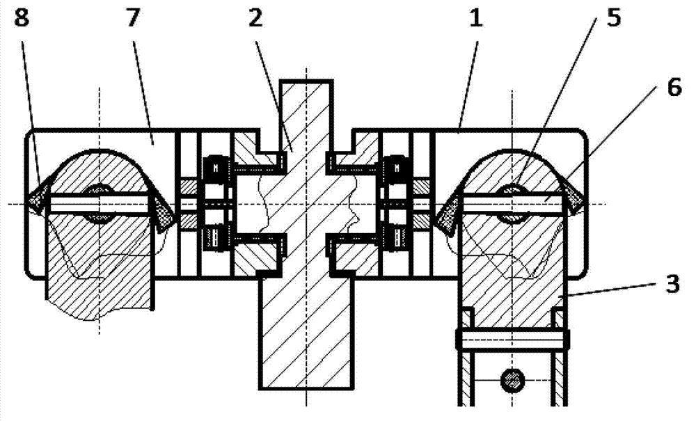
[0021] The simulated hip joint prosthesis of the present invention takes the right hip joint as an example, and the overall structure of the hip joint is as attached figure 1 shown. The main structure of the hip joint is a U-shaped member 1, the torso 2 is used to simulate the human pelvis, and the part 3 is used to simulate the human thigh (or femur). For specific connections, see the attached figure 2 , wherein the hole on the bottom surface of the U-shaped member 1 and the horizontal axis of the frontal surface protruding from the trunk 2 form a revolving pair to realize the front and rear swing of the thigh 3 (referred to as: hip swing joint); the two side plates of the U-shaped member 1 are coaxial The two holes of the thigh form another rotation pair through a shaft fixed to the thigh 3 to realize the left and right side swin...


PUM


Abstract

The invention discloses a dynamic hip joint prosthesis, and adopts an MDOF (multi-degree of freedom) multi-shaft joint design scheme. The dynamic hip joint prosthesis includes U-shaped components (1), a trunk part (2) and thigh end parts (3), which form a hip forward and backward swing joint and a hip side swing joint. The joint moving range is ensured through bosses (7) on side plates of the U-shaped components (1), the impact when the joints reach limit positions are absorbed through soft baffle blocks (8), the friction force is adjusted through lock nuts (11) and further the joint damping is adjusted; and a sensor (12) is mounted through a sensor support (13), so that the joint angular displacement can be measured in real time. The simulated hip joint model can realize hip joint forward and backward swing and inward and outward swing, the joint damping can be adjusted, a trunk can keep a posture under the condition of no external force, and the motion angle can be measured by the sensor in real time.

Description

technical field [0001] The invention belongs to the field of bionic structure design. It can be used in the design of hip joints for robots, lower body trainers, aviation catapults or car safety crash dummy, and can also be used as a reference for other joint designs. Background technique [0002] The hip joint connects the lower limbs and the pelvis and is an important joint of the human body. Its degrees of freedom of movement include flexion, extension, and rotation, which belong to multi-freedom multi-axis joints. In the overall structural design of the robot and the dummy, it is necessary to realize two degrees of freedom of swinging back and forth and swinging inside and outside, and the range of motion conforms to the data of human anatomy. The human body achieves complex movements through the cooperation of the femur and the acetabulum, and controls joint stability through ligaments. However, the design of the dummy's hip joint is quite difficult. Not only must it...

Claims


Application Information

Patent Timeline
IPC IPC(8): F16M11/12F16C11/04
Inventor 柳松杨王颉贾晓红
Owner AVIATION MEDICINE INST AIR FORCE PLA
Why Eureka
Try Eureka