
Method for monitoring dynamic fractures of underground mining working face

A working face and fracture technology, which is applied in the field of monitoring dynamic fractures at the front end of the well mining working face in the sandstorm area, can solve the problems of high fluidity, inability to obtain the life cycle of front end fractures, and difficulty in identifying and selecting observation objects.

Active Publication Date: 2012-10-31
CHINA SHENHUA ENERGY CO LTD +1
View PDF3 Cites 16 Cited by
  • Summary
  • Abstract
  • Description
  • Claims
  • Application Information

AI Technical Summary

Problems solved by technology

[0010] 1) The identification and selection of observation objects is very difficult: the surface of the wind-blown sand area with thin bedrock is covered by loose layers, and the soil above the scour layer is mainly composed of yellow sand with high mobility. The influence of plasticity is greater, and the representation of the initial stage of surface cracks on the surface is relatively weak. Compared with other types of areas, it is very difficult to distinguish and select its characteristics. Therefore, the data of the initial state of the ground cracks when they are generated and the final life cycle of the cracks are obtained. had a great impact;
[0011] 2) It is difficult to obtain the geometric information of fractures: the presence of floating sand layers on the surface in the sandstorm area, the soil on both sides of the cracks is too sandy and loose in texture, and part of the soil on the crack wall is prone to collapse during the cracking and closing process of the cracks. phenomenon, which brings great difficulties to the acquisition of crack width data. Uncertain accidental errors introduce gross errors, and the expected effect cannot be achieved. In the end, the life cycle of the front crack cannot be obtained.

Method used


Image

  • Method for monitoring dynamic fractures of underground mining working face
  • Method for monitoring dynamic fractures of underground mining working face
  • Method for monitoring dynamic fractures of underground mining working face

Examples


Embodiment

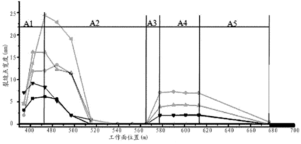
[0050] Embodiment: Aiming at the monitoring of mining cracks in a certain mining area, the crack width information obtained by the above method is used to draw a trend diagram of the crack width advancing with the working face, as shown in image 3 As shown, there are 5 observation points on the crack, where ■ represents 1#, ● represents 2#, ▲ represents 3#, Represents 4# and Represents 5#.

[0051] When the front working face is 454m away from the cutting hole, the crack appears first, 7m ahead of the working face; when the working face advances 19m, the crack shows the largest sign, and the 5# information collection point increases from 3.3mm to about 25mm, The change speed is about 1.158mm / m. This area corresponds to the A1 stage. In this stage, the fracture widths of the four information collection points #1, #2, #3, and #4 are all increasing, which belongs to the fracture development stage.

[0052] When the working face continued to move forward for 42m, the width o...


PUM


Abstract

The invention relates to a method for monitoring dynamic fractures of an underground mining working face, which is used for accurately and completely obtaining mining subsidence fractures and geometric information in the development process thereof. The method comprises the steps as follows: a fracture monitoring reference line is laid; a mathematical model between the position of a fracture at the headmost end of the working face and the position of the working face is established; a corresponding best observational fracture is found out through the mathematical model, so as to be observed continuously and dynamically; variation data of fracture width is obtained; and a variation trend chart of the fracture width relative to the position of the working face is drawn, so as to facilitate the analysis of characteristics and time node information at all typical stages experienced by the headmost fracture in the whole process from the production to total closure, summarize and abstract the complete life cycle of the dynamic fracture at the headmost end of the work face, and then provide a time reference and technical support for the study of an influence mechanism of coal mining of an area over the land ecological environment and the self-repairing cycle of the land ecological environment.

Description

technical field [0001] The invention relates to the technical field of environmental monitoring, in particular to a monitoring method for dynamic cracks at the front end of an underground mining working face in a sandstorm area. Background technique [0002] The main mining area in the wind-sand area has unique soil physical and chemical properties. For example, in the Shendong area of ​​China, due to desertification and potential desertification, the soil particles in the wind-sand area are relatively coarse, loose and unstructured, and have poor water storage and fertilizer retention. The existing thin topsoil layer disintegrates quickly, and the soil particles are easily dispersed. In addition, the physical and chemical properties of the soil interact with harsh climatic factors such as heavy rain and strong wind, causing serious soil erosion. These conditions and factors ultimately lead to a very fragile ecological environment in the mining area. [0003] Relevant stud...

Claims


Application Information

Patent Timeline
Patent Type & Authority Applications(China)
IPC IPC(8): G01B21/04
Inventor 顾大钊胡振琪王新静张建民郭雨明
Owner CHINA SHENHUA ENERGY CO LTD
Learn More