Laser range finder

A technology of laser range finder, laser beam, applied in the field of range finder

Inactive Publication Date: 2012-10-31
HONG FU JIN PRECISION IND (SHENZHEN) CO LTD +1
View PDF0 Cites 12 Cited by
  • Summary
  • Abstract
  • Description
  • Claims
  • Application Information

AI Technical Summary

Problems solved by technology

The laser range finder can only get the distance of one point on the measured object,

Method used


Image

  • Laser range finder
  • Laser range finder
  • Laser range finder

Examples


Embodiment Construction

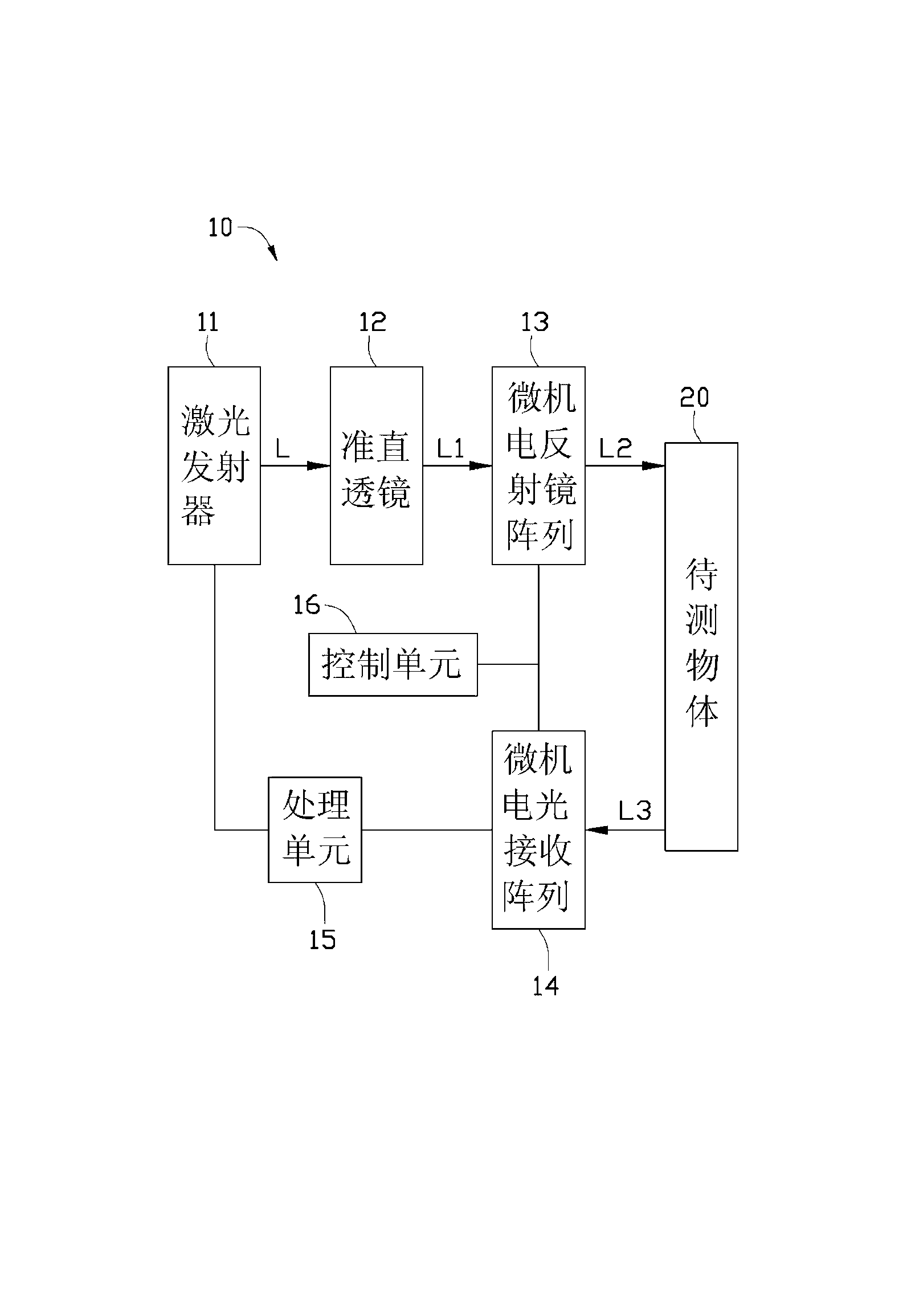
[0014] see figure 1 , figure 2 and image 3 , the laser rangefinder 10 of the embodiment of the present invention comprises a laser transmitter 11, a collimating lens 12, a microelectromechanical mirror array 13, a microelectromechanical light receiving array 14, a processing unit 15 and a control unit 16, and the processing unit 15 is used for recording laser The time when the transmitter 11 emits laser light and the time when the microelectromechanical light receiving array 14 receives the laser light.

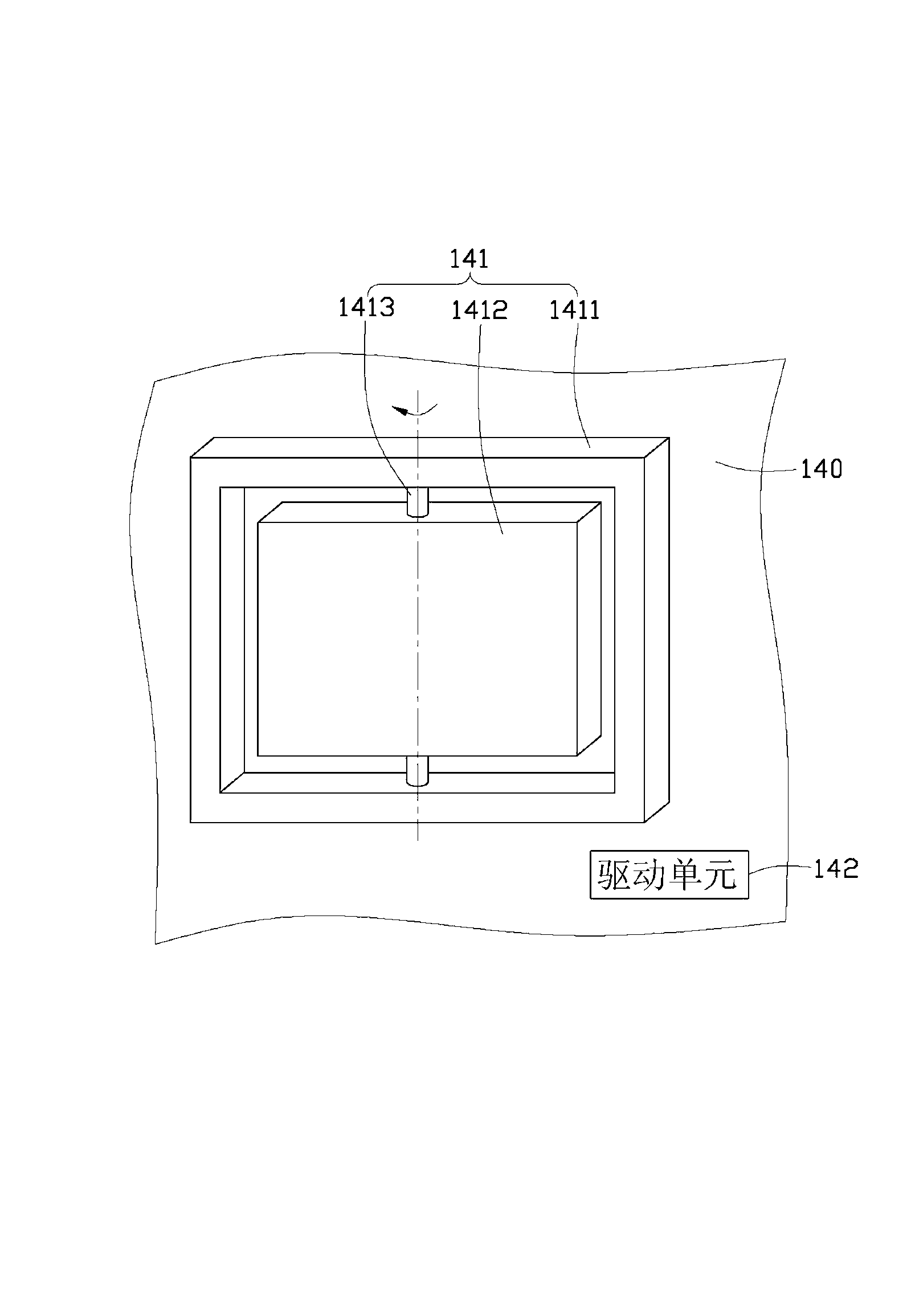
[0015] The micro-electromechanical mirror array 13 and the micro-electromechanical light-receiving array 14 are made by microlithography electroforming (Lithography Electroforming Micro Molding) technology.

[0016] The laser emitter 11 is used to emit a laser beam and emit it onto the collimator lens 12 .

[0017] The collimating lens 12 receives the laser beam emitted by the laser emitter 11 and forms a parallel beam to emit on the MEMS mirror array 13 . Of course, th...


PUM


Abstract

A laser range finder comprises a laser transmitter for transmitting a laser beam, a microcomputer electric reflector array, a microcomputer electro-optical receiving array, and a processing unit. The microcomputer electric reflector array is used for reflecting the laser beam to a plurality of positions on an object to be detected. The microcomputer electro-optical receiving array is used for receiving the laser beam reflected by the object to be detected. The processing unit is used to record transmitting time t1 of the laser beam by the laser transmitter and receiving time t2 of the laser beam reflected by the plurality of positions on the object to be detected through the microcomputer electro-optical receiving array. A plurality of distances to be detected are obtained through the formula t2-t1=2L/c, wherein c is light speed and L is the distance to be detected.

Description

technical field [0001] The invention relates to a range finder, in particular to a laser range finder. Background technique [0002] At present, in addition to direct measurement with a ruler, the existing distance measurement method also includes measurement with a pole and an instrument, and calculates the corresponding angle to calculate the distance. [0003] However, because the length of the ruler is limited, the ruler method is not suitable for long-distance measurement, and the disadvantage of using a pole to measure with an instrument is that one person needs to insert the pole while the other controls the instrument. The method is labor-intensive, and in the measurement of a long distance, this method is inconvenient and prone to large errors. [0004] In recent years, the laser distance measurement method has been widely used in distance measurement, and the laser distance meter has also become an important tool for distance measurement. Noisy, high-sensitivity ...

Claims


Application Information

Patent Timeline
IPC IPC(8): G01S17/08G01S7/481
Inventor 赖志成
Owner HONG FU JIN PRECISION IND (SHENZHEN) CO LTD
Why Eureka
Try Eureka