Microwave antenna subsystem

A microwave antenna and subsystem technology, applied in the field of antenna sub-antennas, can solve problems such as electromagnetic wave leakage and affect the overall performance of the antenna, and achieve the effects of preventing electromagnetic interference, weakening electromagnetic electrostatic effects, and reducing antenna electromagnetic losses.

Active Publication Date: 2012-10-31
KUANG CHI INST OF ADVANCED TECH +1
View PDF13 Cites 7 Cited by
  • Summary
  • Abstract
  • Description
  • Claims
  • Application Information

AI Technical Summary

Problems solved by technology

[0003] In the prior art, the reflective surface and the feed source of the microwave antenna are usually connected together by a single connector such as a screw, so there must be a gap between the feed source and the reflective surface
In the low-frequency field, this gap will not have a great impact on the performance of the antenna, but in the high-frequency microwave field, this gap will cause a large amount of leakage of electromagnetic waves and affect the overall performance of the antenna

Method used


Image

  • Microwave antenna subsystem
  • Microwave antenna subsystem
  • Microwave antenna subsystem

Examples


Embodiment Construction

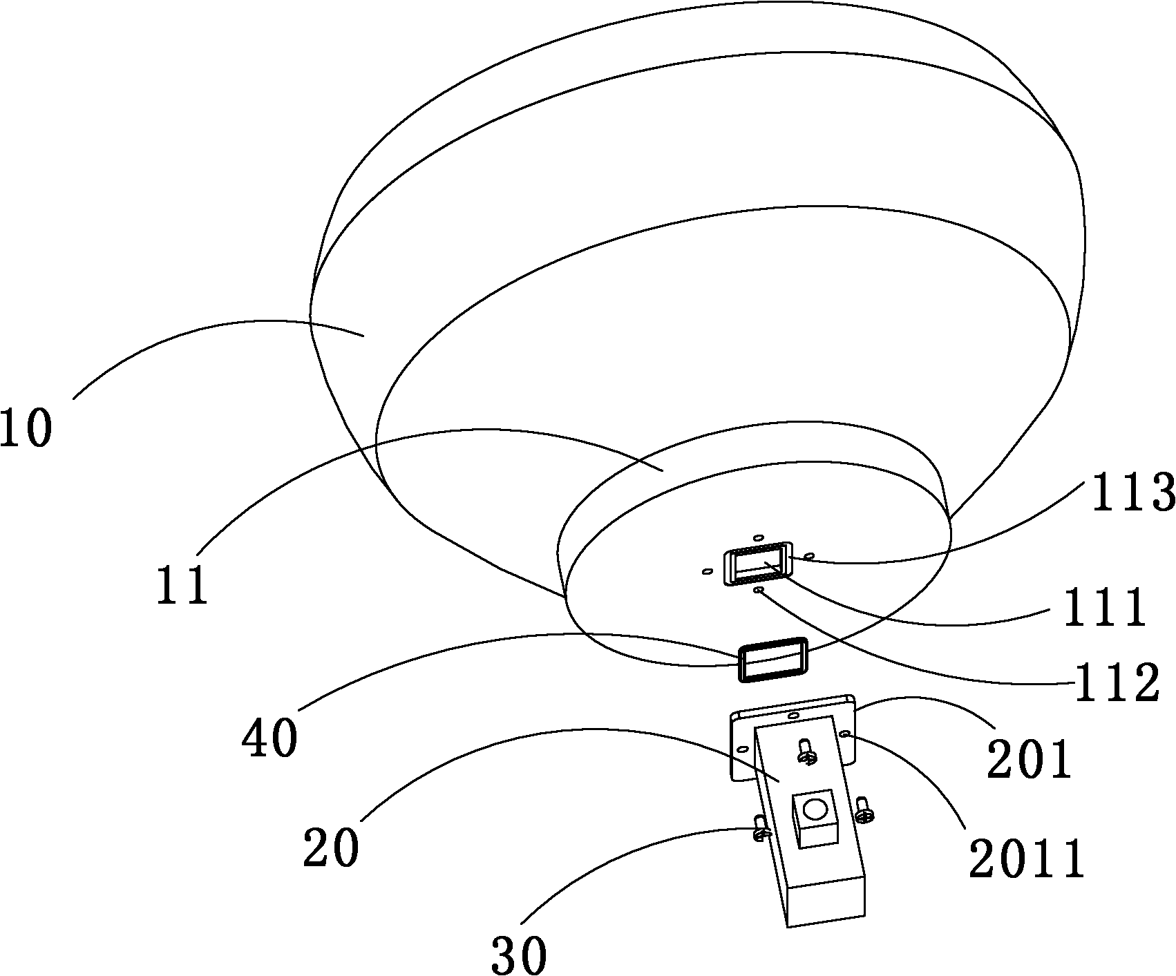
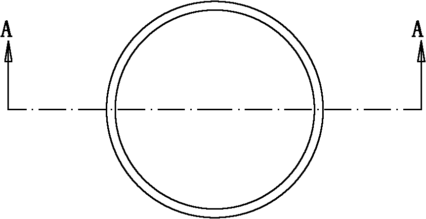
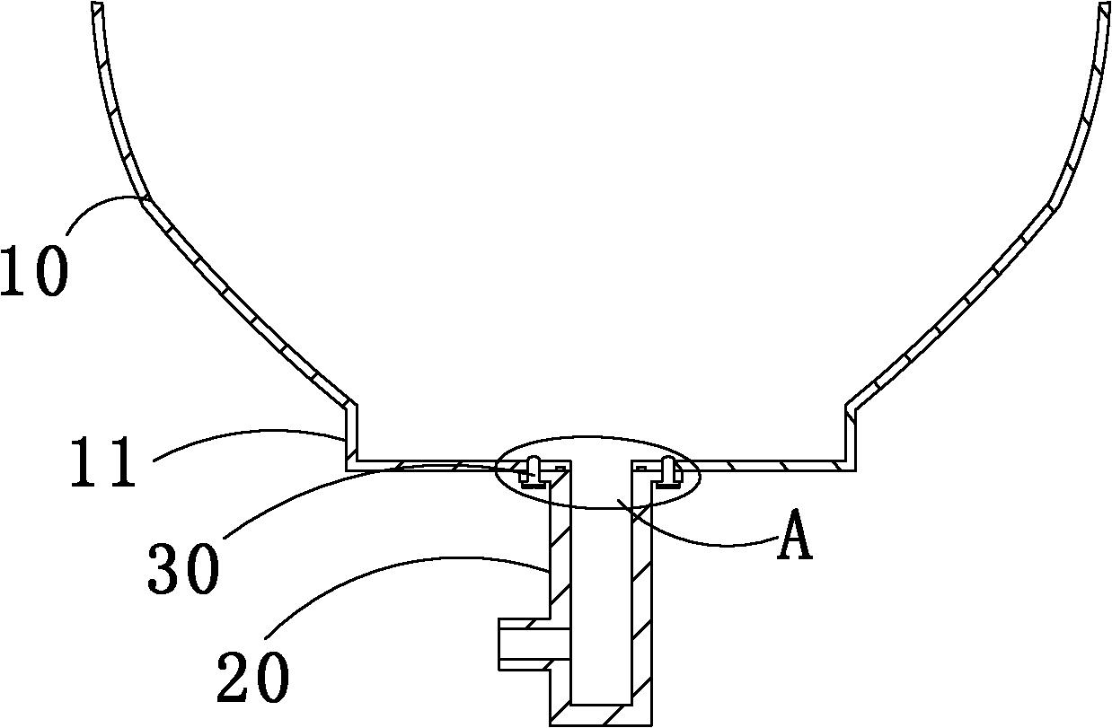
[0022] Please refer to figure 1 , figure 2 , image 3 , Figure 4 . figure 1 It is an exploded exploded view of the microwave antenna subsystem of the present invention, figure 2 is the front view of the microwave antenna subsystem of the present invention, image 3 It is the A-A sectional view of the microwave antenna subsystem of the present invention, Figure 4 for image 3 Enlarged view of part A in . The microwave antenna subsystem of the present invention includes an integrally injection-molded metal reflective surface, a feed source 20 and a sealing ring 40, and a plurality of screws 30 pass through a plurality of first threaded holes 2011 provided on the feed source 20 and are disposed on the end of the metal reflective surface. 11 to lock the feed source 20 and the metal reflective surface.

[0023] The metal reflective surface includes a parabolic main body 10 and a cylindrical end 11 , the main body 10 and the end 11 are integrally formed and hollow inside...


PUM


Abstract

The invention relates to a microwave antenna subsystem which comprises a metal reflecting surface and a feed source, wherein a port of the feed source for transmitting or receiving electromagnetic waves is corresponding to a through hole at the bottom of the metal reflecting surface. The microwave antenna subsystem also comprises a seal ring arranged between the metal reflecting surface and the feed source, the seal ring seals the metal reflecting surface and the feed source and prevents electromagnetic leakages, and the seal ring is placed in a groove formed from the metal reflecting surface and the feed source and is fixedly connected with the metal reflecting surface, the feed source and the seal ring. With the seal ring, electromagnetic leakages of an antenna during high-frequency microwave communication can be effectively prevented, electromagnetic loss is reduced, and antenna performance is increased.

Description

technical field [0001] The present invention relates to an antenna sub-antenna, in particular to a microwave antenna sub-system. Background technique [0002] The microwave antenna is an important part of the microwave relay communication system. It mainly includes a parabolic reflector and a feed source. The feed source is located on the lower side of the reflector to transmit or receive electromagnetic waves. The electromagnetic waves emitted from the feed source are reflected by the reflective surface to be emitted to the outer space, and the electromagnetic waves emitted from the outer space are also converged to the feed source through the reflective surface. [0003] In the prior art, the reflective surface and the feed source of the microwave antenna are generally connected together through a single connecting piece such as a screw, so there must be a gap between the feed source and the reflective surface. In the low-frequency field, this gap will not have a great im...

Claims


Application Information

Patent Timeline
Patent Type & Authority Applications(China)
IPC IPC(8): H01Q1/00H01Q1/52H01Q19/10H01Q19/13
Inventor 刘若鹏尹武徐冠雄
Owner KUANG CHI INST OF ADVANCED TECH
Why Eureka
Try Eureka