High-power density magnetic compression power generation mechanism and electric generator comprising same

A high power density, magnetic compression technology, applied in electrical components, electromechanical devices, etc., can solve the problems of insufficient power density of power generation units, limited power generation efficiency ratio, large size of power generation devices, etc., to improve space utilization and improve the magnetic circuit. , Improve the effect of induced electromotive force

Active Publication Date: 2019-07-26
BEIJING INSTITUTE OF TECHNOLOGYGY
View PDF6 Cites 1 Cited by
  • Summary
  • Abstract
  • Description
  • Claims
  • Application Information

AI Technical Summary

Problems solved by technology

The space reserved for the relative movement between the coil and the permanent magnet will also occupy a larger volume of the power generating device.
This has greatly restricted the ratio of the power generation efficiency of the power generation mechanism to its volume, resulting in the problems of insufficient power density and low integration of traditional power generation units

Method used


Image

  • High-power density magnetic compression power generation mechanism and electric generator comprising same
  • High-power density magnetic compression power generation mechanism and electric generator comprising same
  • High-power density magnetic compression power generation mechanism and electric generator comprising same

Examples


Embodiment Construction

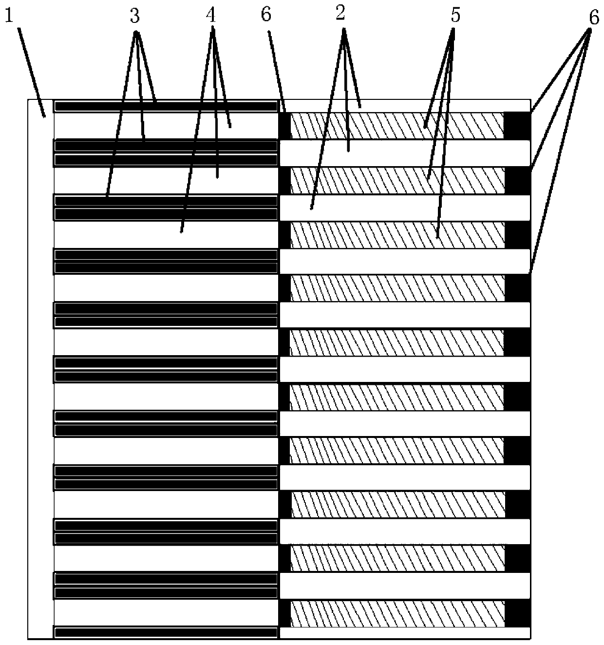
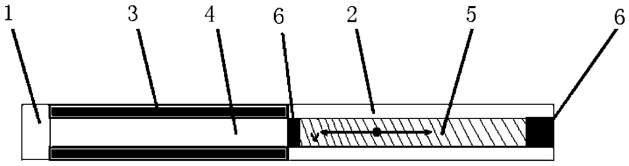
[0028] Refer to as figure 1 and 2 As shown, the high power density magnetic compression power generation mechanism of this embodiment includes: a stator part and a mover part that can move relatively.

[0029] The stator part includes a strip-shaped first stator core 1, and a plurality of second stator cores 2 which are independently arranged from the first stator core 1 and are perpendicular to the first stator core 1. The second stator cores 2 are distributed and arranged in parallel, that is, there is a gap between two adjacent second stator cores 2 . Moreover, a group of boneless coils 3 is arranged between the end of each second stator core 2 and the first stator core 1, and the gaps between the plurality of second stator cores 2 are respectively the same as those of the plurality of second stator cores 2. The gaps between the boneless coils 3 communicate to form a plurality of parallel linear motion spaces 4 .

[0030] Specifically, the first stator core 1 , the secon...


PUM


Abstract

The invention discloses a high-power density magnetic compression power generation mechanism. The high-power density magnetic compression power generation mechanism comprises a stator part and a rotorpart, wherein the stator part comprises first stator iron cores, and a plurality of second stator iron cores which are independent from the first stator iron cores and are vertically arranged; the plurality of second stator iron cores are distributed in parallel; a frame-free coil is arranged between the end part of each second stator iron core and the first stator iron core, and the gaps betweenthe plurality of second stator iron cores are communicated with the gaps between the plurality of frame-free coils to form a plurality of linear motion spaces; the rotor part comprises a plurality ofstrip-shaped permanent magnets which are in parallel and a rotor which is connected with the strip-shaped permanent magnets; and the plurality of permanent magnets are inserted into the linear motionspaces respectively, and high-frequency reciprocating movement is carried out under the driving of the rotor, so that the magnetic flux of the frame-free coils changes violently in the short time, and high electric potential is induced. The invention also discloses an electric generator comprising the power generation mechanism. According to the mechanism, the magnetic flux of the coil changes violently in the short time through high-frequency translation movement, so that high-power density power generation is realized.

Description

technical field [0001] The invention relates to the technical field of power generation, in particular to a high power density magnetic compression power generation mechanism and a generator including the same. Background technique [0002] The power generation principle of the power generation mechanism is mainly to use the electromagnetic induction phenomenon to generate an induced electromotive force in the coil by changing the magnetic flux in the coil, and the magnitude of the induced electromotive force is related to the number of turns of the coil and the change of the magnetic flux passing through the coil The rate is directly proportional. Therefore, in order to obtain a higher induced electromotive force, for the parameter design of the generator itself, it should have a stronger magnetic field environment and more coil turns. [0003] At present, in the power generation mechanism that uses permanent magnets to provide a magnetic field environment, the power gener...

Claims


Application Information

Patent Timeline
Patent Type & Authority Applications(China)
IPC IPC(8): H02K35/02
CPCH02K35/02
Inventor 邹渊孙逢春董玉刚张旭东杜国栋
Owner BEIJING INSTITUTE OF TECHNOLOGYGY
Why Eureka
Try Eureka