
Method for temperature measurement

A technology for temperature measurement and temperature measurement, which is applied to thermometers, measuring devices, and heat measurement. It can solve the problems of high cost and limited production quantity, and achieve the effect of increasing power consumption and realizing simple principles.

Active Publication Date: 2012-10-31
TEKNOLOGIAN TUTKIMUSKESKUS VTT
View PDF3 Cites 6 Cited by
  • Summary
  • Abstract
  • Description
  • Claims
  • Application Information

AI Technical Summary

Problems solved by technology

[0003] Existing sensor tags use expensive custom ICs, are produced in limited quantities, and require specific instructions and readers

Method used


Image

  • Method for temperature measurement
  • Method for temperature measurement
  • Method for temperature measurement

Examples


Embodiment Construction

[0024] Next, principles and examples in accordance with the present invention are discussed more thoroughly.

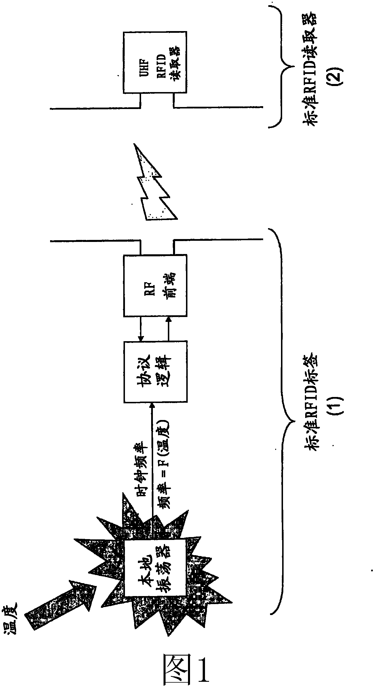
[0025] according to figure 1 , the temperature affects the frequency of the on-chip oscillator of the RFID tag 1 . The tag 1 is read by an RFID reading device 2 . The frequency of the Tag 1 local oscillator is determined by a method described in detail later in this document. The protocol is intentionally made insensitive to this frequency change. Using suitable methods, the tag clock frequency can be determined. Labeling frequency is proportional to temperature.

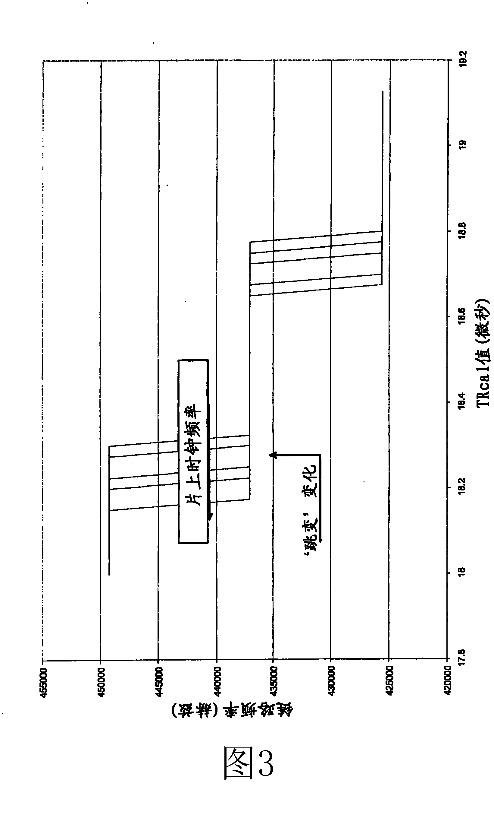
[0026] according to Figure 6 a and 6b, in order to remove the largest noise and unknown parameters, the temperature is stepped up or down.

[0027] Assume the following scenario:

[0028] The internal oscillator of a UHF (Ultra High Frequency) tag is usually based on a ring oscillator

[0029] The frequency of the ring oscillator is proportional to the label temperature

[0030] The dependence of ...


PUM


Abstract

This document describes a method for measuring temperature. In accordance with the invention the temperature is determined from frequency variation of a local oscillator of a RFID tag (1).

Description

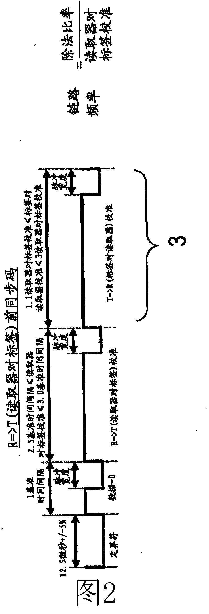
technical field [0001] The present invention generally relates to temperature measurement. [0002] In particular, the method relates to temperature measurement using radio frequency identification (RFID) technology. Background technique [0003] Existing sensor tags use expensive custom ICs, are produced in limited quantities, and require specific instructions and readers. Contents of the invention [0004] It is therefore an object of the present invention to provide a new method of temperature measurement. [0005] This invention describes how standard RFID tags can be used to remotely measure ambient temperature without the need for specific instructions or custom tags. The principle is described using the 2nd generation EPC (Electronic Product Code) protocol, but the principle can also be applied to other tags including an on-chip oscillator. The measurement is based on the frequency variation of the tag's internal oscillator and the preamble of the transmitted EPC...

Claims


Application Information

Patent Timeline
Patent Type & Authority Applications(China)
IPC IPC(8): G01K1/02G01K7/32G06K19/077
CPCG01K1/024G01K7/32
Inventor J·拉米H·塞帕
Owner TEKNOLOGIAN TUTKIMUSKESKUS VTT
Learn More