Square cabin, manufacturing method of square cabin and generator set using square cabin

A manufacturing method and shelter technology, applied in the direction of engine components, machines/engines, supporting machines, etc., can solve problems such as loud noise, noise pollution, and reduced working efficiency of generator sets, and achieve the effect of reducing weight and noise pollution

Active Publication Date: 2012-11-07
浙江幸福航天科技有限公司
View PDF7 Cites 6 Cited by
  • Summary
  • Abstract
  • Description
  • Claims
  • Application Information

AI Technical Summary

Problems solved by technology

The general power source is to obtain power by connecting the load to the grid, but in some cases, such as the grid is damaged or cannot be connected to the grid in the wild, in order to maintain the normal operation of the load, a generator set is required
[0003] Existing generator sets are very noisy when they are in use, which will cause serious noise pollution. Therefore, they are generally placed in a closed anechoic environment for sound insulation and noise reduction, but in this way, the heat generated during the working process of the generator set will be reduced. It will be stored in a closed and anechoic environment, which will reduce the working efficiency of the generator set and cause serious safety hazards

Method used


Image

  • Square cabin, manufacturing method of square cabin and generator set using square cabin
  • Square cabin, manufacturing method of square cabin and generator set using square cabin
  • Square cabin, manufacturing method of square cabin and generator set using square cabin

Examples


specific Embodiment 1

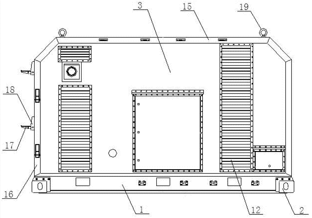
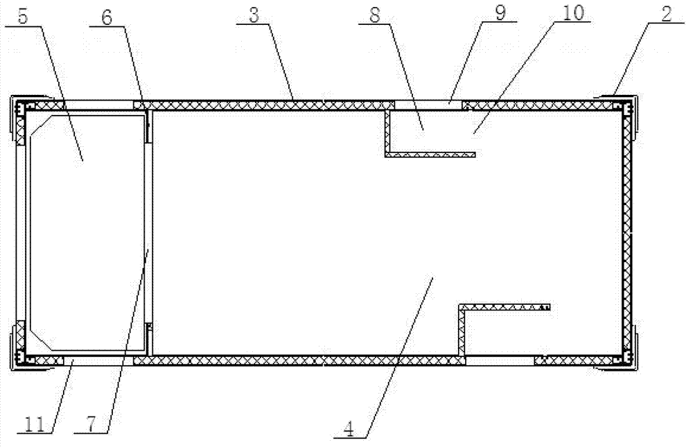
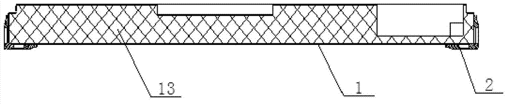
[0069] like Figures 1 to 4 As shown, the shelter includes a base 1 and a frame; the frame is arranged on the base 1; a top plate and a plurality of side plates 3 are embedded in the frame; the shelter is jointly surrounded by the base 1, the top plate, side plates 3 and the frame; the shelter Divided into the equipment compartment 4 and the air outlet compartment 5, the equipment compartment 4 and the air outlet compartment 5 are separated by a partition 6; the partition 6 is provided with an air guide port 7; the inner side of the side plate 3 is provided with a porous metal plate; The inner side of the side plate of the equipment compartment 4 is connected with a detour air duct 8; the air inlet 9 of the detour air duct 8 is located on the side panel 3 connected thereto; and at least one turn is included between the air inlet 9 and the air outlet 10 of the detour air duct 8 The side plate 3 that constitutes the air outlet chamber 5 is provided with an air outlet 11; the air...

specific Embodiment 2

[0074] like Figure 5 Shown, the manufacture method of shelter, comprises the following steps:

[0075] 201) Make frame;

[0076] 202) The step of bonding the side plate and the porous metal plate together by pressing is specifically: laying the surface metal plate, the glass fiber cotton plate and the porous metal plate together sequentially, and pressing them into shape;

[0077] 203) Embedding the top plate and the side plate attached to the porous metal plate in the frame, and setting a circuitous air duct, a partition, and an air exhaust port;

[0078] 204) Making a base with a cavity inside;

[0079] 205) filling the cavity with a foaming agent;

[0080] 206) Foaming the blowing agent to form a foam that fills the entire cavity;

[0081] 207) Connect the frame and the base as a whole.

[0082] Wherein, steps 201 to 203 and steps 204 to 206 can be performed simultaneously, or steps 204 to 206 can be performed first, and then steps 201 to 203 can be performed.


PUM


Abstract

The invention relates to the field of power supply, in particular to a square cabin, a manufacturing method of the square cabin and a generator set using the square cabin. The square cabin is enclosed jointly by a base, a top plate, side plates and a frame, wherein porous metal plates are arranged inside the side plates. The insides of the side plates which form a device cabin are connected with bypass wind tunnels. At least one turn is arranged between an air inlet and an air outlet of each bypass wind tunnel. Exhaust ports are arranged on the side plates which form an air-out cabin. The manufacturing method of the square cabin comprises the steps of: manufacturing the frame; pressing the side plates and the porous metal plates together; embedding the top plate and the side plates into the frame and arranging the bypass wind tunnels and the exhaust ports; manufacturing the base; and connecting the frame and the base into a whole. The generator set comprises the square cabin and an engine and generators in the square cabin. The porous metal plates are arranged inside the side plates so as to absorb noise in the square cabin effectively. The bypass wind tunnels are arranged to absorb part of sound waves in the condition of meeting the requirements of ventilation and heat rejection, thereby further reducing the noise.

Description

technical field [0001] The invention relates to the field of power supply, in particular to a shelter, a manufacturing method of the shelter and a generator set using the shelter. Background technique [0002] With the development of society, electricity has become an indispensable energy source in people's daily life. The general power source is to obtain power by connecting the load to the grid, but in some cases, such as the grid is damaged or cannot be connected to the grid in the wild, at this time, in order to maintain the normal operation of the load, a generator set is required. [0003] Existing generator sets are very noisy when they are in use, which will cause serious noise pollution. Therefore, they are generally placed in a closed anechoic environment for sound insulation and noise reduction, but in this way, the heat generated during the working process of the generator set will be reduced. It will be stored in a closed and anechoic environment, which will re...

Claims


Application Information

Patent Timeline
Patent Type & Authority Applications(China)
IPC IPC(8): F16M1/00F16M1/08F02B77/13F02B63/04
Inventor 徐阐阐彭宇林席晓宁
Owner 浙江幸福航天科技有限公司
Why Eureka
Try Eureka