Device for measuring elevation position variation at different levels of monitoring points and application method
A technology for monitoring points and elevations, applied to measuring devices, instruments, etc.
- Summary
- Abstract
- Description
- Claims
- Application Information
AI Technical Summary
Problems solved by technology
Method used
Image
Examples
Embodiment approach 1
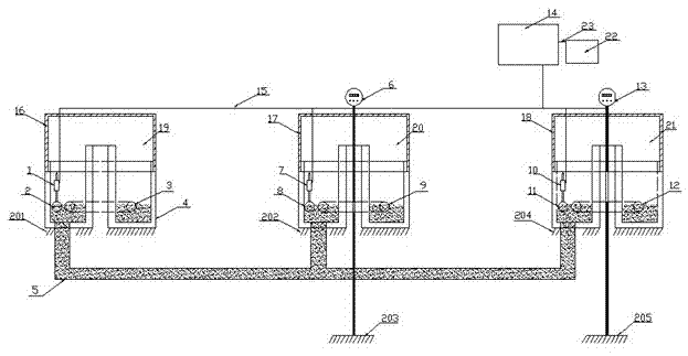
[0059] Implementation mode 1: The device consists of a first liquid level sensor 1, a first floating ball 2, a first floating magnetic ring 3, an inert water 4, a pipeline 5, a first micro-deformation sensor 6, a second liquid level sensor 7, and a second floating ball 8 , the second floating magnetic ring 9, the third liquid level sensor 10, the third floating ball 11, the third floating magnetic ring 12, the second micro-deformation sensor 13, the data collector 14, the connection line 15, the first cover 16, the second Two cover 17, the 3rd cover 18, the first bowl body 19, the second bowl body 20, the 3rd bowl body 21, computer 22 form, as figure 1 As shown, the monitoring device is composed of three monitoring bowls, the first bowl 19 is the reference monitoring point, the second bowl 20 and the third bowl 21 are used for the purpose of real-time deformation monitoring. Then the liquid level difference between the initial moment of the first bowl 19 and the i-th moment...
Embodiment approach 2
[0061] Implementation mode 2: In the case of Embodiment 1, the third bowl 21 is removed, and the device consists of the first bowl 19 and the second bowl 20 to form a connecting device. The first bowl 19 is the reference monitoring point, and the second bowl 20 is used for real-time deformation monitoring. , the same as in Embodiment 1, the calculation formula lacks the part where the fourth monitoring point 204 and the fifth monitoring point drop, that is
[0062] ?H 201i =(?H 202下 ) / 2
[0063] ?H 202i =(?H 202下 ) / 2
[0064] ?H 203下 =?H 203i +(?H 202下 ) / 2
[0065] In the same way, it can be concluded that ?H 202203 is ?H 202203 =?H 202下 -?H 203下 , according to ?H 202203 If the value is , the synchronization of the deformation of the monitoring point 202 and the monitoring point 203 can be obtained. The larger the difference, the worse the synchronization of the deformation.
Embodiment approach 3
[0066] Implementation mode 3: In the case of Embodiment 1, the fourth bowl 22 is added, and the device is composed of the first bowl 19, the second bowl 20, the third bowl 21 and the fourth bowl 22 to form a connecting device, and the first bowl 19 is used as the reference monitoring point, the second pot body 20, the third pot body 21 and the fourth pot body 22 are used as the purpose of real-time deformation monitoring, same as embodiment 1, here there are more sixth monitoring point 206, seventh monitoring point 207, then in the calculation formula The descending parts of the sixth monitoring point 206 and the seventh monitoring point 207 are added. Through the above three implementation methods, the formula can be summarized as follows:
[0067] Let 20S be the S monitoring point, and t be the total number of bowls (t≥2).
[0068] Then? H 201i =(?H 202下 +...+?H 20S下 ) / t {s=2n,n=1,2,...,2(t-1)}
[0069] ?H 20Si =[(t-1)?H 20S下 ] / t-(?H 202下+...+?H 20[2(t-1)]下 -?H 2...
PUM
 Abstract
Description
Claims
Application Information
 - R&D
- Intellectual Property
- Life Sciences
- Materials
- Tech Scout
- Unparalleled Data Quality
- Higher Quality Content
- 60% Fewer Hallucinations
Browse by: Latest US Patents, China's latest patents, Technical Efficacy Thesaurus, Application Domain, Technology Topic, Popular Technical Reports.
© 2025 PatSnap. All rights reserved.Legal|Privacy policy|Modern Slavery Act Transparency Statement|Sitemap|About US| Contact US: help@patsnap.com

