
Combined bone holding forceps

A bone-holding pliers and combined technology, applied in the field of medical devices, can solve the problems of single fixed style and specification, no reservation, limited contact surface, etc., and achieve cumbersome and unsafe operation, high reset efficiency, and firm clamping Effect

Inactive Publication Date: 2012-11-14
贝朝涌
View PDF9 Cites 2 Cited by
  • Summary
  • Abstract
  • Description
  • Claims
  • Application Information

AI Technical Summary

Problems solved by technology

However, due to the different sizes and shapes of bones and fracture types, the existing bone forceps and other similar instruments have many problems, and it is difficult to meet the needs of surgery.
Wherein the main defect has: 1. The shape of the bone is generally irregular, and the part of the bone-holding instrument adopts a fully symmetrical fixed arc-shaped jaw at the clamping position, and the contact surface with the bone is limited. This type of instrument is often used in clinical operations due to The clamping bone is unstable and slips, causing the fracture end to puncture the surrounding blood vessels, nerves and soft tissues, which is likely to cause serious medical accidents
2. There is no space reserved for internal fixation materials in the jaws, especially when the plate is implanted, the bone clamp needs to be loosened, and then clamped again after the plate is implanted, which may easily lead to poor reduction of the fracture
3. The contact between the bone forceps and the bone is often designed with horizontal stripes parallel to the long bones, which makes it easy for the bone forceps to slip laterally
4. There are many types of bone holding forceps and other similar instruments, but most of them are relatively fixed in style and specification, and it is difficult to deal with different types of fracture reduction

Method used


Image

  • Combined bone holding forceps
  • Combined bone holding forceps
  • Combined bone holding forceps

Examples


Embodiment 1

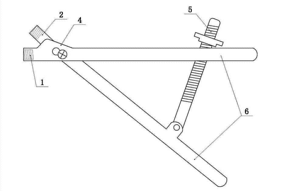
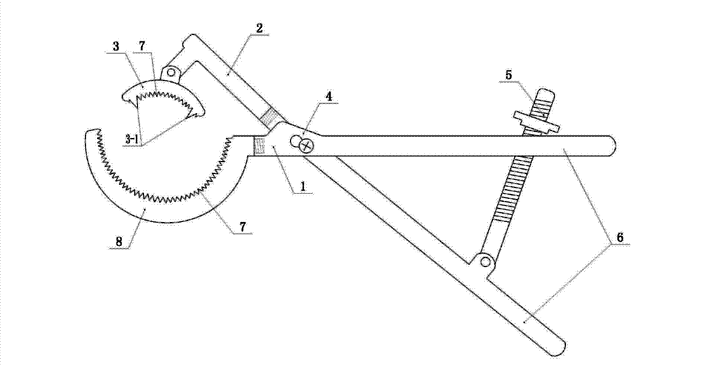
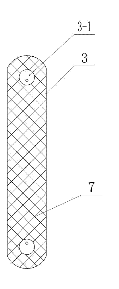
[0023] refer to Figure 1-Figure 6 , a swinging head bone holding forceps, comprising upper forceps arm 2, lower forceps arm 1, upper forceps head 3, lower forceps head 8, sharp teeth 3-1, movable main joint 4, adjustable screw rod 5, forceps handle 6 and mesh texture7. The upper pliers arm 2 and the lower pliers arm 1 of the bone holding forceps have exactly the same interface, and can be connected with different types of replaceable pliers heads. The lower pincer head 8 is arc-shaped, and the pincer head is larger. Upper pincer head 3 is a swing-type pincer head, and its center is arranged on an axle, and the pincer head can swing along the axis, and the axle is arranged on a connecting device, and the connecting device is screwed with upper pincer arm 2 . The lower pliers arm 1 is connected with a lower pliers head 8 . The clamping surfaces of the upper pliers head 3 and the lower pliers head 8 of the combined bone holding forceps are provided with a mesh texture 7, and ...

Embodiment 2

[0026] refer to figure 1 , Figure 7 , The upper pincer head 3 is a trident universal pincer head, which is directly screwed on the upper pincer arm, and the rest are the same as in embodiment 1.

Embodiment 3

[0028] refer to figure 1 , Figure 8 , The upper pincer head 3 is a nail-tooth type pincer head, which is directly screwed on the upper pincer arm, and the rest are the same as in embodiment 1.


PUM


Abstract

The invention discloses a pair of combined bone holding forceps, which comprises forcep handles, forcep arms, forcep heads, an X-shaped forcep body which is in cross-linked form in which the forcep arms and the forcep heads in crossed connection, a movable main joint on the forcep body, adjustable screws on the forceps handles and forcep heads, wherein the forcep handles are straight rods, arc rods or S-shaped rods. The combined bone holding forceps are characterized in that an upper forcep arm and a lower forcep arm of the bone holding forceps are provided with interfaces which are the same completely, and the interfaces can be connected with different types of replaceable forcep heads. The forcep heads of the bone holding forceps are provided with a plurality of alternative types; the alternative types can be selected according to the size and the shape of the bones and the type of bone fracture; the upper and lower forcep heads can be replaceable in positions, convenient to use and high in resetting efficiency; the forcep heads are movable forcep heads, and the forcep heads can be selected and adjusted according to the shape of the bone so as to increase contact surface with the bone, so that clamping is firmer; a certain space for arranging an internal fixation material is preserved between the clamping surfaces of the two forcep heads, so that the problem that existing appliances are fussy in operation and unsafe is solved. Netlike texture is arranged on the clamping surfaces of the bone holding forceps, and the bone does not easily slip when being clamped.

Description

technical field [0001] The invention belongs to the field of medical instruments, in particular to a combined bone holding forceps. Background technique [0002] Fractures are one of the most common diseases in orthopedics. At present, in fracture open reduction and internal fixation surgery, instruments such as bone forceps are often used to clamp the two broken ends of the fracture for reduction, and then fix with internal fixation materials. But because the size and shape of the bone and the type of fracture are different, there are many problems in the existing bone-holding forceps and other similar instruments, which are difficult to meet the needs of the operation. Wherein the main defect has: 1. The shape of the bone is generally irregular, and the part of the bone-holding instrument adopts a fully symmetrical fixed arc-shaped jaw at the clamping position, and the contact surface with the bone is limited. This type of instrument is often used in clinical operatio...

Claims


Application Information

Patent Timeline
Patent Type & Authority Applications(China)
IPC IPC(8): A61B17/28A61B17/56
Inventor 贝朝涌徐威粟谋黄芹蒋林彬
Owner 贝朝涌
Learn More