Distal fibular anatomic bone plate

A technology of bone plate and distal end, applied in the direction of outer plate, internal bone synthesis, medical science, etc., can solve the problems of high suture tension of the skin, pain of the patient, weakened holding force, etc., and achieve low skin tension, reduce pain, and improve strength Effect

Active Publication Date: 2014-09-24
ZHEJIANG CANWELL MEDICAL DEVICES CO LTD
View PDF10 Cites 1 Cited by
  • Summary
  • Abstract
  • Description
  • Claims
  • Application Information

AI Technical Summary

Problems solved by technology

Kirschner wires, tension bands, screws, etc. lack strong fixation to the distal end of the fracture, and cannot fully meet the requirements of reduction and fixation
Although the ordinary bone plate has a certain fixing strength, it must be shaped, which affects the strength of the plate, and is thicker, and the suture tension of the skin is high, which is prone to complications such as delayed skin healing and infection, especially for comminuted fractures of the distal fibula , bone fragments far from the syndesmosis or osteoporotic comminuted fractures, the distal fractures are still difficult to meet the requirements of fixation
The existing anatomical bone plate or ordinary locking bone plate does not have multi-directional fixation with screws. For distal comminuted fractures or decreased bone density, the screws are easy to loosen, the holding force is weakened, and the screws are easy to enter the joint cavity. Cause clinical application difficulties, affect the therapeutic effect, and cause pain to patients

Method used


Image

  • Distal fibular anatomic bone plate
  • Distal fibular anatomic bone plate
  • Distal fibular anatomic bone plate

Examples


Embodiment 1

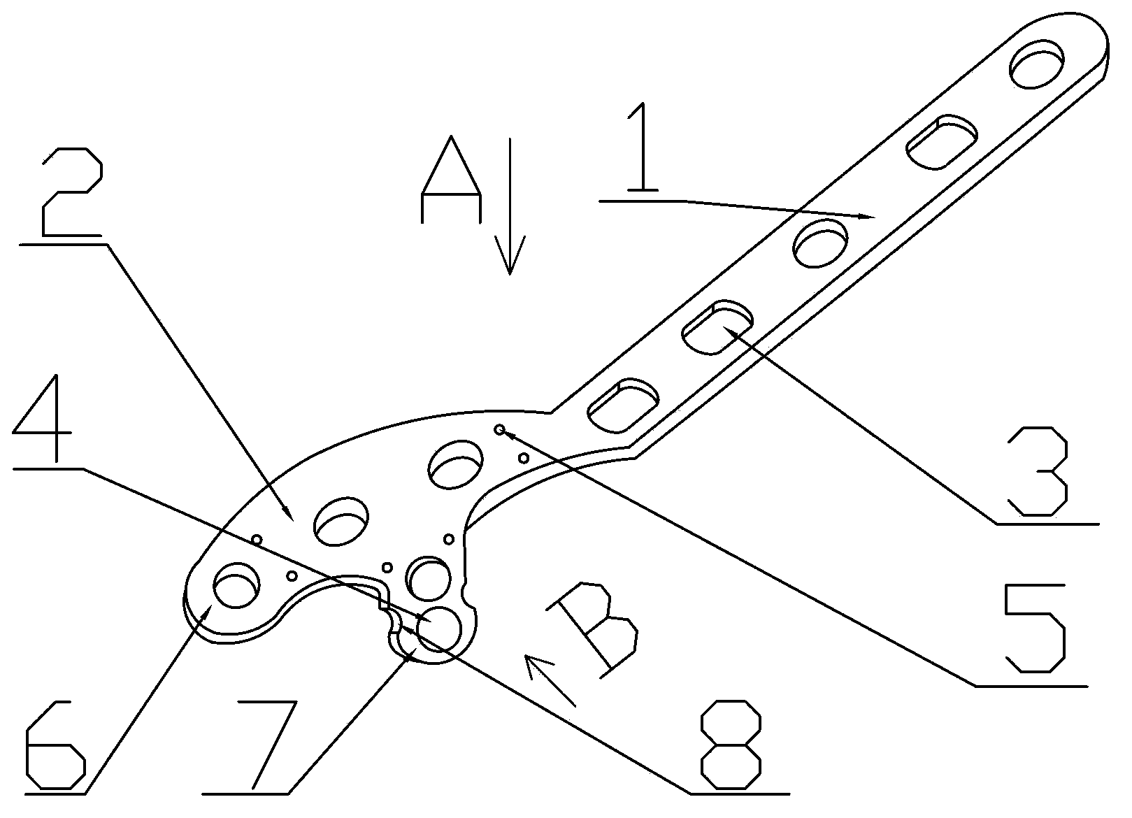
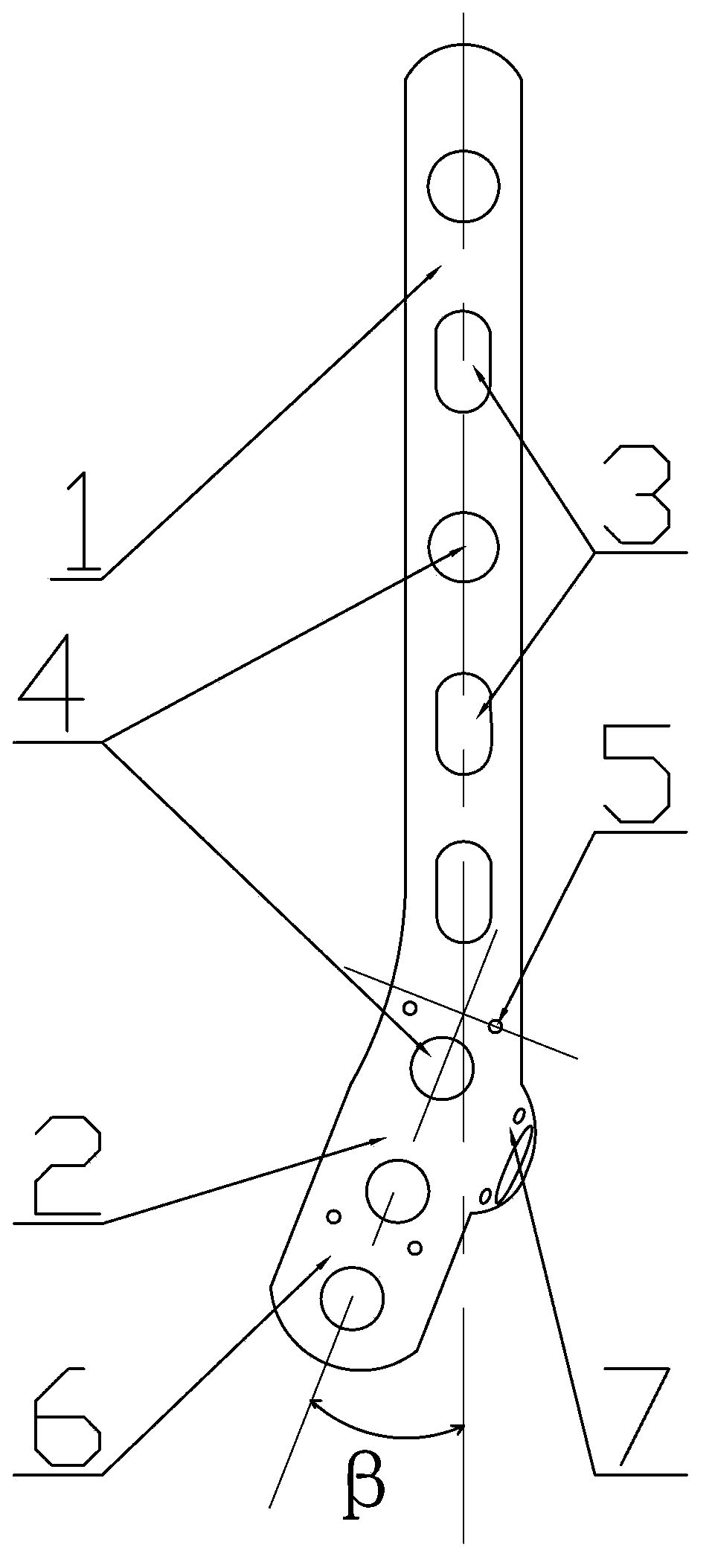
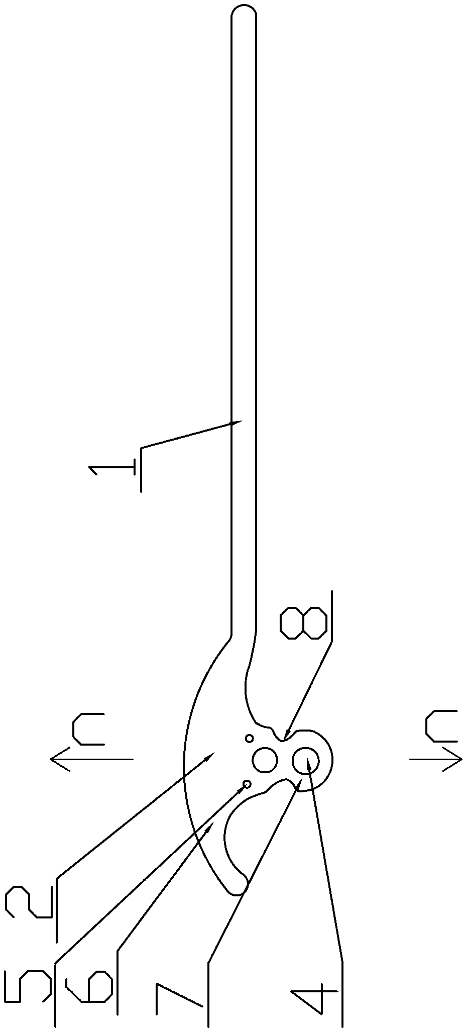
[0014] An anatomical bone plate for distal fibula flank, comprising a stem main board 1 and a flank main board 2, said stem main board 1 is provided with 3 locking and pressurizing screw holes 3 and 2 locking screw holes 4; said flank The mainboard 2 includes a far-end wing plate 6 and a front side wing plate 7. The far-end wing plate 6 is provided with 3 locking screw holes 4 and 4 gram pinholes 5, and the front side wing plate 7 is provided with 2 locking screw holes. Holes 4 and 2 gram pinholes 5. The angle α between the inclined surface of the front side wing 7 and the horizontal plane of the highest point of the distal wing 6 is 90°; The included angle β is 30°. The front side wing plate 7 is designed to be provided with a narrow and thin arc-shaped reconstruction belt 8, so that the main body main board 1 and the side wing main board 2 are matched with each other in a curved shape that matches the distal end of the fibula, and fits more closely to the outer surface of t...

Embodiment 2

[0017] An anatomical bone plate for distal fibula flanks, comprising a stem main board 1 and a flank main board 2, the stem main board 1 is provided with 3 locking pressurization holes 3, and no locking screw holes 4 are provided; the flank main board 2 Including the distal wing plate 6 and the front side wing plate 7, the distal wing plate 6 is provided with 3 locking screw holes 4 and 2 grams pinholes 5, and the front side wing plate 7 is provided with 2 locking screw holes 4 and 2 gram pinholes 5. The angle α between the inclined surface at the end of the front side wing plate 7 and the plane of the highest point of the distal wing plate 6 is 100°, and the distance between the central axis of the main body main board 1 and the central axis of the distal wing plate 6 is 100°. The angle β between them is 0°, at this time, the main body main board 1 and the distal wing plate 6 are on the same straight line. The front wing 7 is designed as a narrow and thin arc-shaped reconstr...

Embodiment 3

[0020] An anatomical bone plate for distal fibula flanks, comprising a stem main board 1 and a flank main board 2, the stem main board 1 is provided with 2 locking pressurization holes 3 and 1 locking screw hole 4; the flank main board 2 Including the distal wing plate 6 and the front side wing plate 7, the distal wing plate 6 is provided with 5 locking screw holes 4 and 4 grams pinholes 5, and the front side wing plate 7 is provided with 2 locking screw holes 4 and 2 gram pinholes 5. The locking screw holes on the distal wing plate 6 are smaller in diameter than the locking screw holes on the main body main board 1. The locking screw holes on the distal wing plate 6 are not distributed in a single row. The screw holes on the side wing main board 2 are designed to be all The distribution in which the screws do not collide with each other. The angle α between the inclined surface at the end of the front side wing plate 7 and the plane of the highest point of the distal wing pl...


PUM

PropertyMeasurementUnit
thicknessaaaaaaaaaa
thicknessaaaaaaaaaa

Abstract

The invention relates to a bone plate, in particular to an anatomical bone plate for the flank of the distal end of the fibula. An anatomical bone plate for the distal side of the fibula, comprising a main body of the main body and a main body of the side wings, the main body of the main body is provided with 3 locking screw holes and 2 locking screw holes; the main body of the side wings includes a distal wing The plate and the front wing plate are designed in the shape of the bone plate that matches the human fibula, which fits better after installation and has less impact on skin tension. At the same time, a locking screw hole is designed on the distal end of the bone plate, so that the locking screw can be fixed in multiple directions. At the same time, through the design of the front wing plate and its screw hole, the screw can be fixed from the front side to the back side during fixation, avoiding entering the fibula The articular surface improves the strength of fixation, and it is convenient to apply in clinical operations, which reduces a lot of pain for patients.

Description

technical field [0001] The invention relates to a bone plate, in particular to an anatomical bone plate for the flank of the distal end of the fibula. Background technique [0002] Ankle fracture is a common intra-articular fracture, and it is one of the most important load-bearing joints of the lower extremity joints. The length and alignment of the lateral malleolus are the most important links in the rehabilitation of the ankle joint, followed by the repair of the medial malleolus and the inferior tibiofibular ligament. Studies have shown that 20% of the upward force in the gait posture is absorbed by the lateral ankle, so strong internal fixation of the fibula is necessary to restore the ideal length of the lateral malleolus and normal valgus angle, restore the anatomical relationship between the distal end of the fibula and the tibia, and maintain the lower tibiofibular joint. anatomy. The distal end of the fibula not only forms the inferior tibiofibular joint with ...

Claims


Application Information

Patent Timeline
Patent Type & Authority Patents(China)
IPC IPC(8): A61B17/80A61L31/02
Inventor 兰树华黄淑明郑荣宗吴泉州吕国强
Owner ZHEJIANG CANWELL MEDICAL DEVICES CO LTD
Why Eureka
Try Eureka