Filtering tank

A filter tank and filter membrane technology, which is applied in the field of filter tanks, can solve the problems of unclean cleaning, short service life of roll-type membranes, and difficult cleaning of roll-type membrane dirt, so as to achieve the effect of easy and easy cleaning of dirt

Active Publication Date: 2014-04-23
BEIJING WANBANGDA ENVIRONMENTAL PROTECTION TECH
View PDF3 Cites 0 Cited by
  • Summary
  • Abstract
  • Description
  • Claims
  • Application Information

AI Technical Summary

Problems solved by technology

[0005] (1) Since the water to be filtered enters from one axial end of the coiled membrane, the residue during filtration not only remains on the filter membrane but also on the filter screen, making it difficult to clean;
[0006] (2) Because every two adjacent wound filter units in the roll membrane are in direct contact with each other too closely, that is, in every two adjacent filter units, the filter membrane of one filter unit is in contact with the other filter unit. The filter screens of the unit are in close contact, which makes the dirt remaining in the roll-type membrane more difficult to clean and not clean when filtering
[0007] To sum up, the existing roll-type membrane is not easy to clean and cannot be cleaned cleanly, so that the filter effect of the roll-type membrane is not good, and the dirt that is not cleaned for a long time will produce green moss, which will also shorten the service life of the roll-type membrane

Method used


Image

  • Filtering tank
  • Filtering tank
  • Filtering tank

Examples


no. 2 example

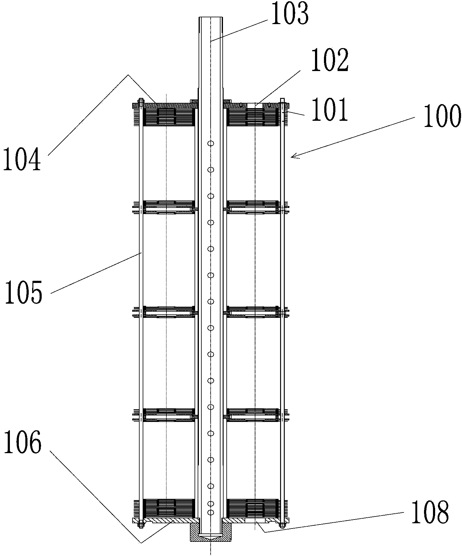
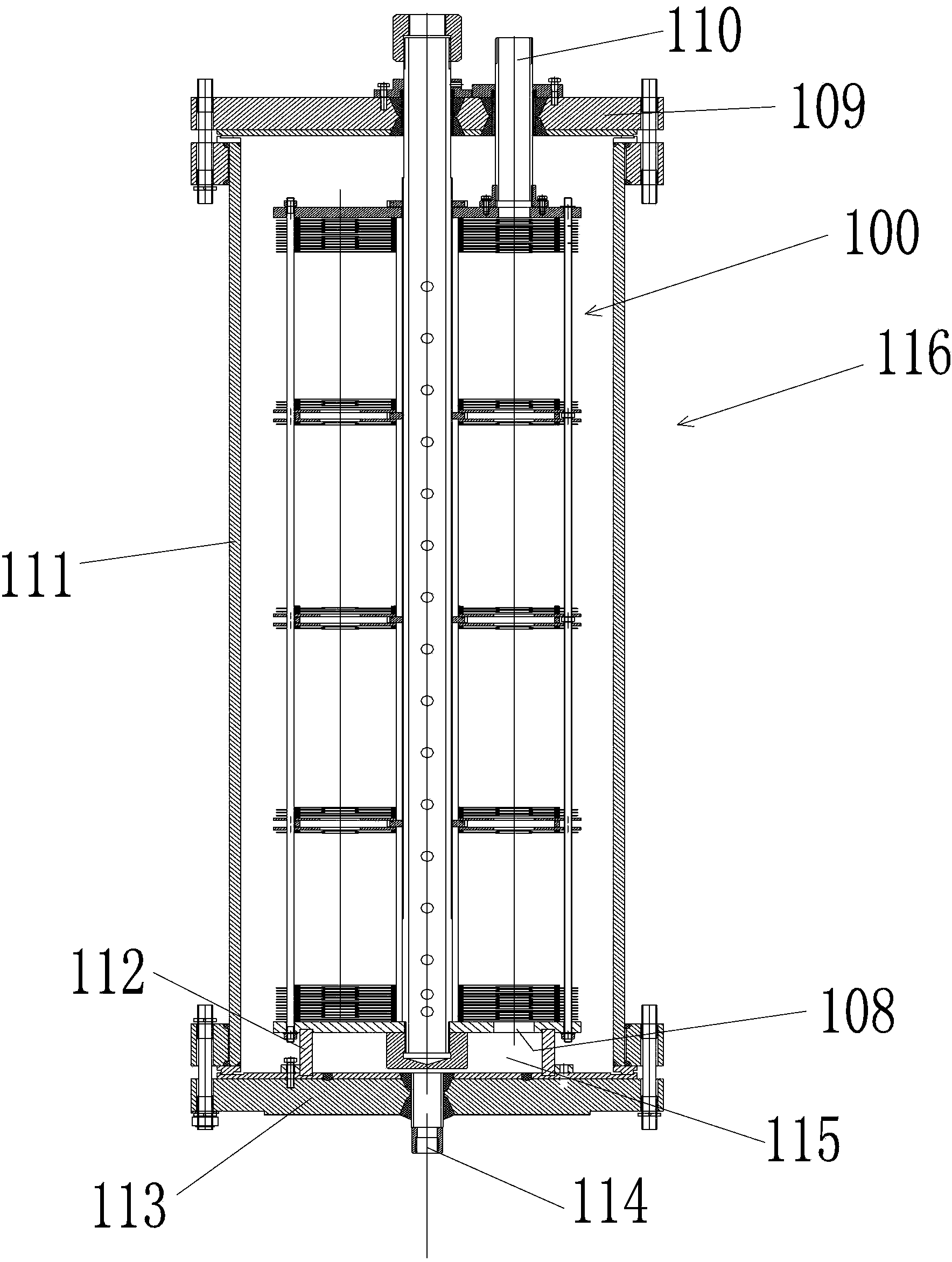
[0051] For the filter unit adopted by the filter core in the filter tank of the present invention, see Figure 3-Figure 7 The first embodiment and the second embodiment of the filter unit are described in detail as follows:

no. 1 example

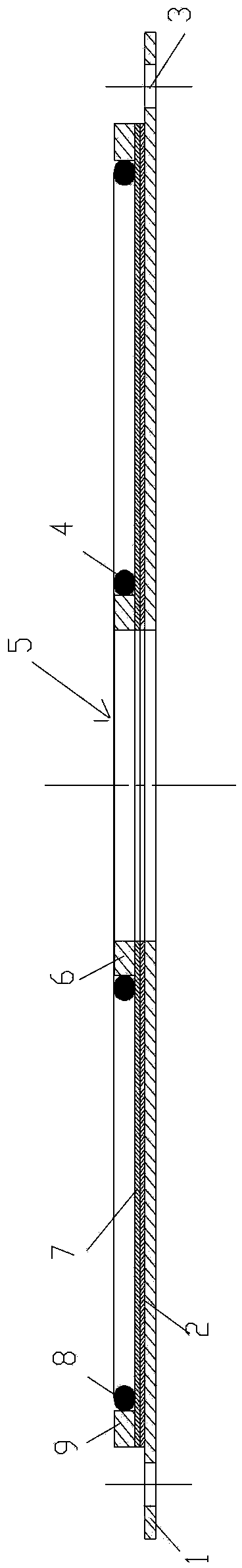
[0053] In order to facilitate a clear understanding of the filter unit in the present invention, first refer to image 3 omits the second perforation (in the Figure 4 Shown in detail) view description, combined with Figure 4 The filter unit showing the second perforation is fully described.

[0054] see image 3 As shown, in this embodiment, the filter unit includes: a stack of laminations, which are formed by a planar rigid water retaining sheet 1, a first filter screen 2, and a first filter membrane 7 stacked sequentially from bottom to top; Group and by water collection pipe 103 ( figure 1 Shown) the first perforation 5 that passes through; the first water retaining ring 6 and the second water retaining ring 9, these two water retaining rings are all laminated on the first filter membrane 7, and the first water retaining ring 6 is on the second In the surrounding area of ​​the second water retaining ring 9 ; and the first perforation 5 is located in the surrounding ar...


PUM


Abstract

The invention provides a filtering tank comprising a tank body (116) and a filtering core (100) accommodated in the tank body (116). The filtering core (100) is provided with a water gathering pipe (103) and a group of filtering units (101), wherein the water gathering pipe (103) penetrates through the tank body (16); the group of filtering units (101) are sleeved on the section, positioned in the tank body, of the water gathering pipe (103); each filtering unit (101) is provided with a water outlet channel and a water gathering channel; water to be filtered flows through the water outlet channel, and the flow path of the water to be filtered on the water outlet channel is provided with a filtering film; and water filtered by the filtering film is delivered to the water gathering pipe (103) by the water gathering channel. The water outlet channels in the filtering units in the filtering core (100) are sequentially communicated with one another end to end and form a water flow channel penetrating through the filtering core round the axis of the water gathering pipe (103). By virtue of the filtering tank, residual dirt during filtering is more easily cleaned.

Description

technical field [0001] The invention relates to a filter tank. Background technique [0002] In the prior art, a conventional filter device for filtering water such as seawater, brackish water, etc. is a filter device with a coiled membrane. The filter membrane and filter screen stacked closely together are an independent filter unit, and such a filter unit is wound on a water collection pipe with radial holes. These filter units wound on the water collection pipe are roll membranes. And there is close contact between every adjacent two wound filter units. [0003] When working, the water to be filtered enters from one axial end of the roll membrane with a certain pressure, and the water entering the roll membrane flows to the water collection pipe along the radial direction of the roll membrane, that is, the water is filtered layer by layer along the radial direction , the filtered water enters the water collection pipe through the radial holes of the water collection pip...

Claims


Application Information

Patent Timeline
Patent Type & Authority Patents(China)
IPC IPC(8): B01D63/10B01D65/02
Inventor 任重
Owner BEIJING WANBANGDA ENVIRONMENTAL PROTECTION TECH
Why Eureka
Try Eureka