Roller drive plate clamping tool

A roll and disc clamping technology, which is applied in the field of roll dial fixtures, can solve the problems of laborious hoisting and positioning, troublesome positioning, etc., and achieve the effects of simple structure, convenient manufacture and use, and saving auxiliary time

Active Publication Date: 2012-11-14
北京信泰德利华自动化科技股份有限公司
View PDF5 Cites 11 Cited by
  • Summary
  • Abstract
  • Description
  • Claims
  • Application Information

AI Technical Summary

Problems solved by technology

There are usually two traditional clamping methods for roll grinding. One is to clamp the dial to drive the roll to rotate after the roll is installed on the grinding machine. This dial is composed of two semi-discs and is generally used in large Roll grinding usually weighs tens of kilograms. Fortunately, a crane can be used to cooperate, but hoisting and positioning are still very laborious
Another way is to put the dial on the roll first and hoist it together with the roll. However, this method is very troublesome for positioning. It is necessary to continuously start the machine tool to adjust the position of the dial. The adjustment and stop must be mastered very well in order to quickly meet the adjustment requirements, otherwise it will take a long time to adjust to a satisfactory effect

Method used


Image

  • Roller drive plate clamping tool
  • Roller drive plate clamping tool

Examples


Embodiment 1

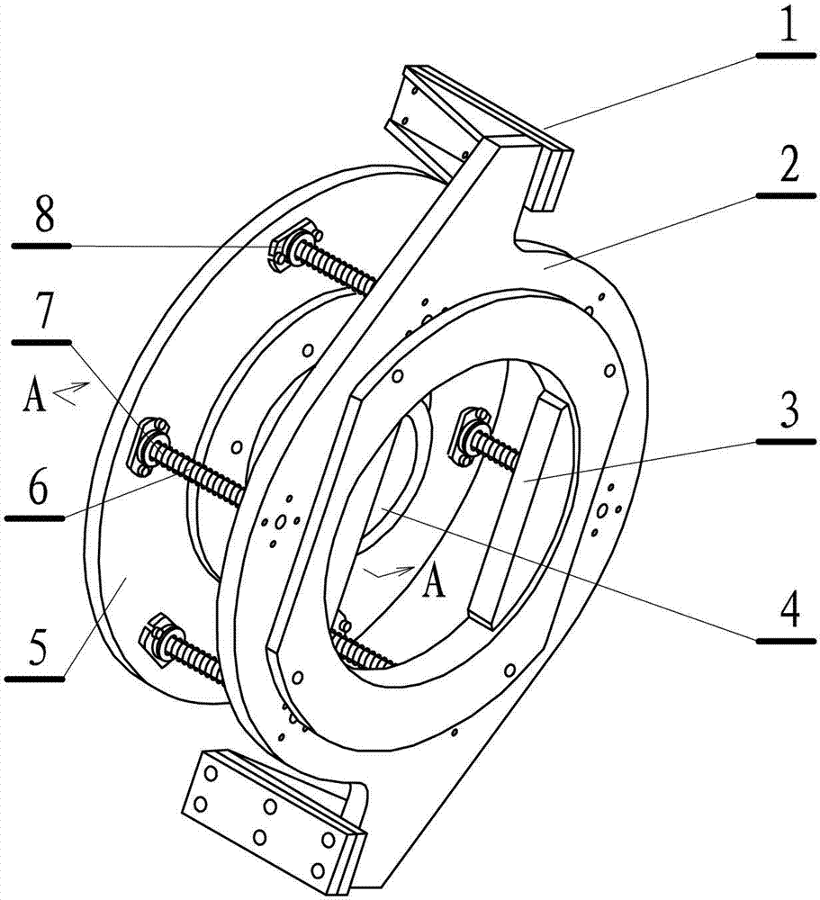
[0010] This embodiment is a roll dial fixture, such as figure 1 shown. This embodiment includes: a disk-shaped sheet-shaped driving disk 2, the outer circumference of the driving disk has a driving claw 1 that matches the shift fork on the main shaft of the roll grinder, and the middle part of the disk is a driving claw that matches the roll driving handle. Holes 3, one end of the driving disc is evenly distributed and fixedly connected to one end of a plurality of support rods 6, and the other end of the support rods passes through the disc-shaped sheet-shaped support disc 5 to set a limit end 9. Springs 7 are sheathed on the support rods, flexible connectors 8 are provided between the support discs and each support rod, and the support discs are connected to the main shaft of the roll grinder through bolts.

[0011] This embodiment is mainly composed of three parts, a support plate fixed on the faceplate of the main shaft of the roll grinder, a drive plate for driving the r...

Embodiment 2

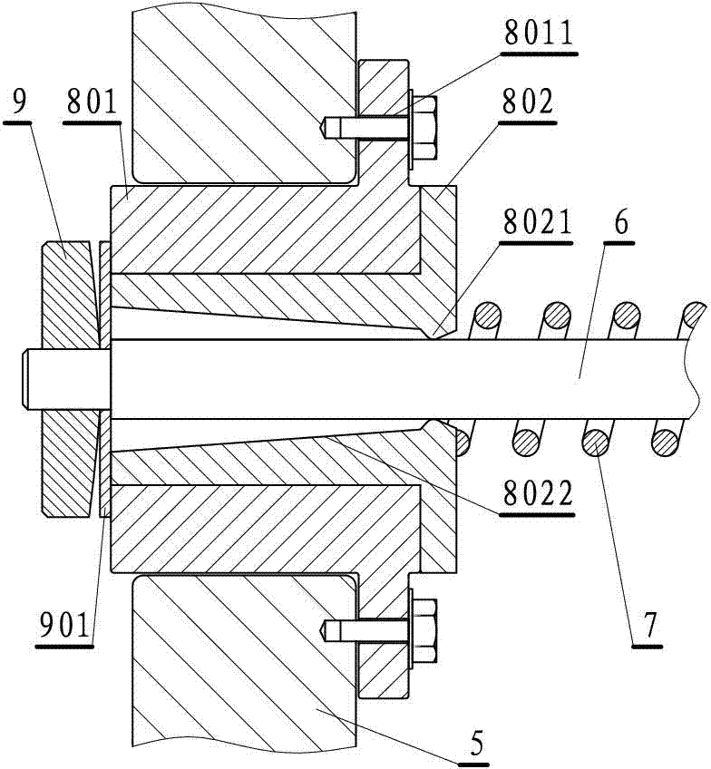
[0021] This embodiment is an improvement of Embodiment 1, and it is a refinement of the embodiment about the flexible connector, such as figure 2 shown. The flexible connector in this embodiment is composed of a fixed sleeve 801 and a guide sleeve 802, the fixed sleeve has a bolt hole 8011 connected with the support plate, the fixed sleeve is fixedly connected with the guide sleeve, The center of the guide sleeve passing through the support rod is a conical hole 8022 with a large port and a small port. The small opening end of the conical hole is provided with a limit ring 8021. The cross-sectional shape of the limit ring is an oblique triangle. The vertices of the oblique triangles are intercepted and replaced by arcs.

[0022] The fixing sleeve described in this embodiment has a mounting claw, and the mounting claw has holes or notches for fixing bolts, and can be fixed on the support plate through the bolts.

[0023] The inner sleeve is the key of the flexible connection...

Embodiment 3

[0026] This implementation is an improvement of the above-mentioned embodiment, and it is a refinement of the above-mentioned embodiment with regard to the limiting end. The contact surface of the limiting end described in this embodiment and the support plate is a circular arc surface, see figure 2 , or a conical surface.

[0027] The arc surface or conical surface limit end described in this embodiment mainly solves the problem of removing the wear between the limit end and the support plate (actually it should be a guide sleeve) due to the swing when the support rod swings. .


PUM


Abstract

The invention relates to a roller drive plate clamping tool. The roller drive plate clamping tool comprises a disc-shaped laminar driver disk, the outer circumference of the driver disk is provided with a drive pawl which is matched with a shifting fork arranged on a roller grinder main shaft, a drive hole which is matched with a roller drive handle is arranged in the middle of a circular disc, one ends of a plurality of supporting rods are uniformly distributed and fixedly connected on the end face of one side of the driver disk, the other ends of the supporting rods penetrate through a disc-shaped laminar support disk to arrange limit end sockets, springs are sleeved on the supporting rods, a flexible connector is mounted between the support disk and each of the supporting rods, and the support disk is connected with the roller grinder main shaft through a bolt. According to the roller drive plate clamping tool, the support disk and the supporting rods are used for connecting the driver disk on a main shaft face plate of a roller grinder in advance, by means of the elastically extending and retracting of the supporting rods, the clamping of a roller is convenient, simultaneously, a flexible connecting mechanism is arranged on the supporting rods, the support disk and the driver disk can relatively twist, and the problem of mutual interference is solved. The clamping tool has the advantages that the structure is simple, the usage is convenient, the work efficiency is increased, and the remarkable economic benefit can be achieved.

Description

technical field [0001] The invention relates to a roll dial clamp, which is a mechanical device and a clamp used for a roll grinding processing center. Background technique [0002] Since the roll is a very heavy part, it generally weighs hundreds to thousands of kilograms. During machining, clamping heavy workpieces to the machine tool is a very difficult task in itself. In some cases, not only the workpiece needs to be hoisted with the crane, but even some fixtures need to be hoisted with the crane because they are too bulky. The problem that arises is that if the design of the fixture is not proper, two cranes need to be used together to complete the clamping of the workpiece. If there are no two cranes to cooperate, the jig needs to be manually moved and loaded, or the jig must be installed on the machine tool before the workpiece is loaded. There are usually two traditional clamping methods for roll grinding. One is to clamp the dial to drive the roll to rotate after...

Claims


Application Information

Patent Timeline
Patent Type & Authority Applications(China)
IPC IPC(8): B24B5/04B24B5/37B24B41/06
Inventor 张茂
Owner 北京信泰德利华自动化科技股份有限公司
Why Eureka
Try Eureka