Check patentability & draft patents in minutes with Patsnap Eureka AI!

Overcurrent and overtemperature protection element

A technology for over-temperature protection and component protection, applied to resistors with negative temperature coefficients, resistors with positive temperature coefficients, etc., can solve the problems of occupying the volume of electronic products and consuming costs

Active Publication Date: 2012-11-14
POLYTRONICS TECH
View PDF4 Cites 9 Cited by
  • Summary
  • Abstract
  • Description
  • Claims
  • Application Information

AI Technical Summary

Problems solved by technology

Therefore, the existing method not only consumes the cost of manufacturing, but also occupies the overall volume of the electronic product.

Method used


Image

  • Overcurrent and overtemperature protection element
  • Overcurrent and overtemperature protection element
  • Overcurrent and overtemperature protection element

Examples


Embodiment Construction

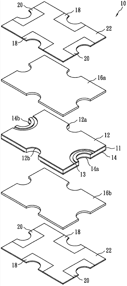
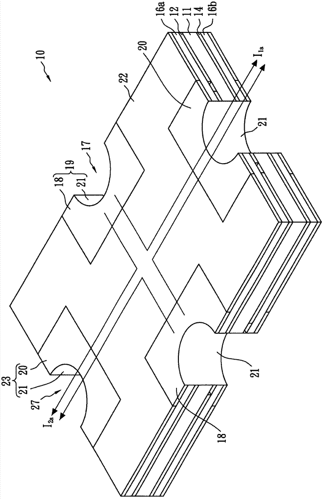
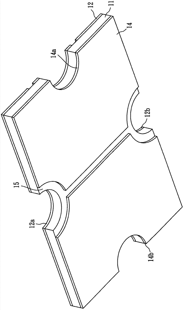
[0064] see Figure 1A to Figure 1C , Figure 1A It is an exploded perspective view of the dual-port overcurrent and overtemperature protection element 10 according to the first embodiment of the present invention. Figure 1B It is a three-dimensional combined view of the first embodiment of the dual-port overcurrent and overtemperature protection element 10 of the first embodiment of the present invention. Figure 1C It is a bottom perspective view of the combination of the resistive element 11 and the upper and lower conductive members 12 and 14 in the dual-port overcurrent and overtemperature protection element 10 according to the first embodiment of the present invention. Figure 1D It is an equivalent circuit diagram of the dual-port overcurrent and overtemperature protection element 10 according to the first embodiment of the present invention.

[0065] The aforementioned over-current and over-temperature protection element 10 is a stacked structure, which includes: a thi...


PUM


Abstract

The invention discloses an overcurrent and overtemperature protection element, comprising: a first conductive member which comprises a power input part and a first insulation part for limiting the input of the current only through the power input part; a second conductive member which comprises at least two power output parts and a second insulation part for limiting the output of the current only through the power output parts, wherein the power output parts are insulated from each other by using the second insulation part; a resistive element stacked between the first conductive member and the second conductive member; a power input part electrode tip electrically connected with the power input part, and a power output part electrode tip electrically connected with the power output part. According to the invention, multiport type overcurrent and overtemperature protection element disclosed herein can simultaneously provide overcurrent and overtemperature protection for two or more loops.

Description

technical field [0001] The invention relates to a passive element, especially to an overcurrent and overtemperature protection element. Background technique [0002] Thermistors are used to protect circuits from being damaged by overheating or excessive current flow. A thermistor usually consists of two electrodes and a resistive material between the two electrodes. This resistance material has a low resistance value at room temperature, and when the temperature rises to a critical temperature or an excessive current is generated on the circuit, its resistance value can immediately jump by more than thousands of times, thereby inhibiting the passage of excessive current to reach the circuit purpose of protection. [0003] When the temperature drops back to room temperature or there is no overcurrent on the circuit, the thermistor can return to a low resistance state, allowing the circuit to operate normally again. This reusable advantage makes thermistors replace fuses an...

Claims


Application Information

Patent Timeline
Patent Type & Authority Applications(China)
IPC IPC(8): H01C7/02H01C7/04
Inventor 曾郡腾王绍裘
Owner POLYTRONICS TECH
Features
  • R&D
  • Intellectual Property
  • Life Sciences
  • Materials
  • Tech Scout
  • Unparalleled Data Quality
  • Higher Quality Content
  • 60% Fewer Hallucinations
Learn More