Combined driving device for performing rotational motion and reciprocating linear motion and linear motor with reduced inertia

A technology of reciprocating linear motion and linear motor, applied in electromechanical devices, electric components, magnetic circuit rotating parts, etc., can solve the problems of inflexible drive devices, etc., and achieve the effect of saving weight and small inertia

Inactive Publication Date: 2012-11-14
SIEMENS AG
View PDF6 Cites 14 Cited by
  • Summary
  • Abstract
  • Description
  • Claims
  • Application Information

AI Technical Summary

Problems solved by technology

[0003] To date, relatively inflexible drives with steering gears have been used in most cases for the realization of combined drives

Method used


Image

  • Combined driving device for performing rotational motion and reciprocating linear motion and linear motor with reduced inertia
  • Combined driving device for performing rotational motion and reciprocating linear motion and linear motor with reduced inertia
  • Combined driving device for performing rotational motion and reciprocating linear motion and linear motor with reduced inertia

Examples


Embodiment Construction

[0046] The examples described in detail below are preferred embodiments of the invention.

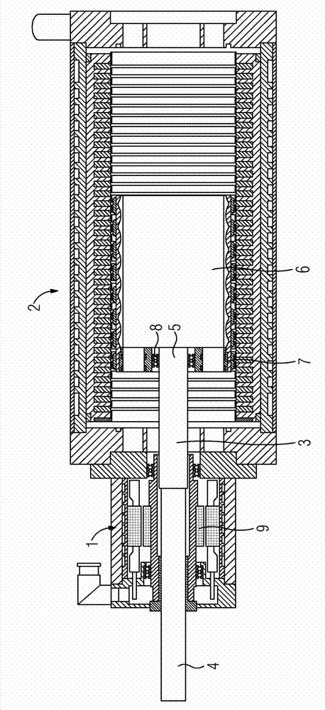
[0047] figure 1 The combined drive for rotary and reciprocating linear movements shown in can be used, for example, in machine tools or robots. It has a rotary motor 1 and a linear motor 2 . Both drive the working axis 3 .

[0048] The combined drive has an output, via which the active power is supplied. exist figure 1 In the embodiment of , the output device is on the left, and the corresponding active power is provided by the working shaft 3 . Accordingly, the working shaft 3 has an output side 4 and a drive side 5 .

[0049] The rotary motor 1 (electric motor for performing a rotary movement or rotary motor) is located closer to the output of the combined drive than the linear motor 2 . However, this also means that the rotary motor 1 is located closer to the output side 4 of the working shaft 3 than the linear motor 2 .

[0050] The working shaft 3 here passes completely thro...


PUM


Abstract

Motive power of a combined driving device or a linear motor should be improved, and accordingly a combined driving device for performing rotational motion and reciprocating linear motion is provided that possesses a rotary motor (1) and a linear motor (2) and an operating shaft (3). The operating shaft (3) can be rotated by the rotary motor (1) to perform rotational motion and can perform linear motion by the linear motor (2); the operating shaft (3) possesses an output side (4). The rotary motor (1) is more closely arranged on the output side (4) of the operating shaft (3) than the linear motor (2). Accordingly the operating shaft (3) can be designed to be shorter. The measure of improving motive power is to reduce rotor quality of the linear motor (2).

Description

technical field [0001] The invention relates to a combined drive device for rotary motion and reciprocating linear motion, which has a rotary motor, a linear motor and a working shaft that can be transferred from the rotary motor to rotary motion and from the linear motor to linear motion. motion, and the working shaft has an output side. Background technique [0002] Combined drives are used for drive tasks that require rotary and linear movements. It is advantageous here that these movements can be freely adjusted independently of one another in terms of angle and path. Furthermore, it is often required that these movements be performed with high dynamics. [0003] To date, comparatively inflexible drives with steering gears have mostly been used for the realization of combined drives. For example, the dynamics of the combined drive can be significantly increased by targeted decoupling of the inertia for linear and rotational movements. In particular, this results in a...

Claims


Application Information

Patent Timeline
IPC IPC(8): H02K41/06H02K1/27H02K5/167
CPCH02K16/00H02K41/031H02K2201/18H02K7/08H02K7/00H02K1/278H02K1/27H02K41/03
Inventor 米夏埃尔·菲克阿明·施特布莱因罗尔夫·福尔默
Owner SIEMENS AG
Why Eureka
Try Eureka