Dryer

The technology of a clothes dryer and a casing is applied in the field of clothes dryers, which can solve the problems of reducing the capacity of the drying room and increasing the capacity of the drum, and achieves the effect of improving the utilization rate of internal space.

Inactive Publication Date: 2012-11-14
LG ELECTRONICS INC
View PDF5 Cites 7 Cited by
  • Summary
  • Abstract
  • Description
  • Claims
  • Application Information

AI Technical Summary

Problems solved by technology

[0006] On the other hand, there is the disadvantage that the capacity of the drying chamber formed by the drum is reduced due to the channel structure for supplying air into the drum
For example, when a drying duct is provided at the rear of the drum to supply dry air into the drum, the space occupied by the drying duct limits the longitudinal length of the drum, thus limiting the capacity increase of the drum

Method used


Image

  • Dryer
  • Dryer
  • Dryer

Examples


Embodiment Construction

[0026] The above and other objects, features, aspects and advantages of the present invention will become more apparent from the following detailed description of the present invention when taken in conjunction with the accompanying drawings. Exemplary embodiments of the present invention will now be described in detail with reference to the accompanying drawings. This invention may, however, be embodied in many different forms and should not be construed as limited to only the embodiments set forth herein. Rather, these embodiments are provided so that this disclosure will be thorough and complete, and will fully convey the scope of the invention to those skilled in the art. In the drawings, the shapes and dimensions of components may be exaggerated for clarity, and the same reference numerals will be used throughout to designate the same or like components.

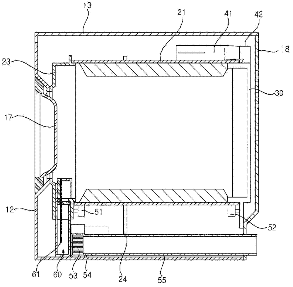
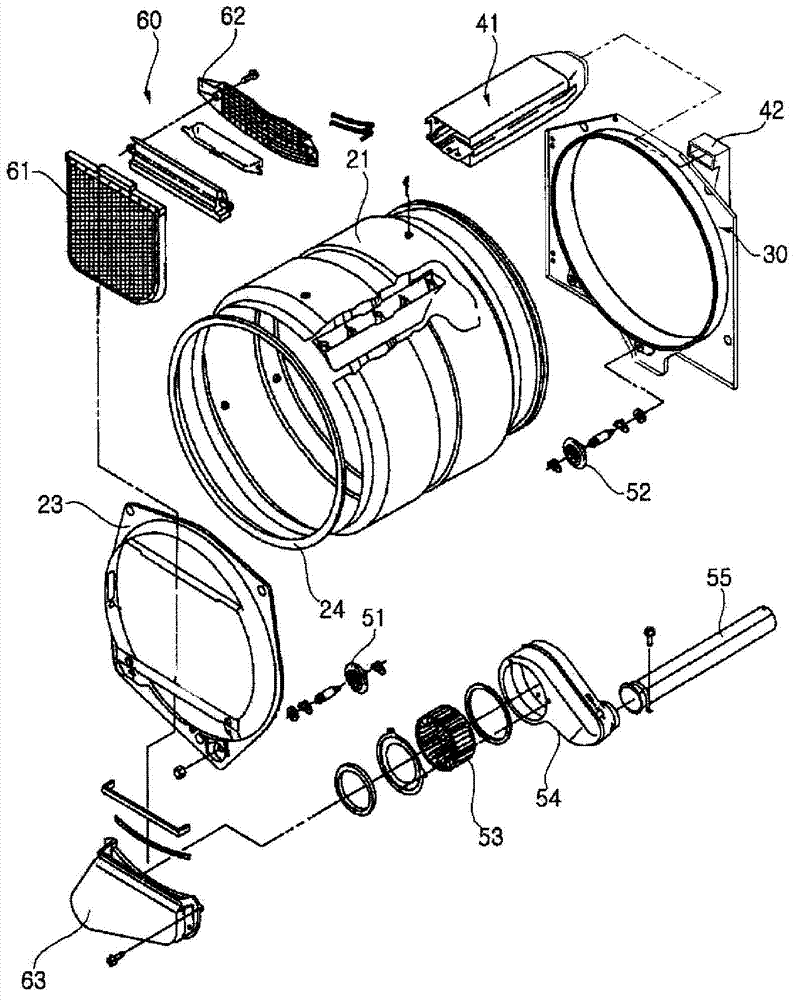
[0027] figure 1 is a perspective view showing a clothes dryer according to an embodiment of the present invention. ...


PUM


Abstract

A dryer is provided. The dryer (1) includes a cabinet (10), a drum (11), a rear supporter (30), and a dry duct (42). The cabinet (10) defines an external appearance. The drum (21) is rotatably provided in the cabinet and housing articles to be dried. The rear supporter (30) supports a rear end of the drum (21). The dry duct (42) supplies dry air. Here, the dry duct (42) is connected to a circumference of the rear supporter (30) to supply the dry air into the drum through the circumference of the rear supporter.

Description

technical field [0001] The present invention relates to a clothes dryer having a greater capacity for items to be dried. Background technique [0002] Generally, a clothes dryer includes a drum, a driving source, a heating source, and a blower. The drum is used to accommodate items to be dried. The driving source is used to drive the drum. Used to draw air into or expel air from the drum. [0003] The clothes dryer may be classified into an electric type clothes dryer and a gas type clothes dryer according to a heating device for heating air. Electric dryers use electrical resistance heat to heat the air, while gas dryers use heat from the combustion of gas to heat the air. [0004] Clothes dryers can also be classified as condensation dryers or exhaust dryers. In a condensation dryer, the air that gets humidified while drying items is circulated rather than exhausted from the dryer. In this case, a separation structure for condensing moisture contained in the circulatin...

Claims


Application Information

Patent Timeline
Patent Type & Authority Applications(China)
IPC IPC(8): D06F58/04
CPCD06F58/04D06F58/02D06F58/20D06F58/26
Inventor 洪硕基金钟锡金成珉朴大润
Owner LG ELECTRONICS INC
Why Eureka
Try Eureka