
Control system provided with programmable display, programmable display, and drawing data creation means thereof

A technology of control system and generation unit, applied in general control system, control/regulation system, program control, etc., to achieve the effect of realizing operation, realizing labor saving, and preventing omission of horizontal expansion

Inactive Publication Date: 2015-03-25
MITSUBISHI ELECTRIC CORP
View PDF5 Cites 1 Cited by
  • Summary
  • Abstract
  • Description
  • Claims
  • Application Information

AI Technical Summary

Problems solved by technology

[0004] The existing control system is configured as above, so it is possible to solve the problem related to the horizontal expansion operation when the common part of the drawing data is changed, but for the unique part of the drawing data, drawing data corresponding to the number of programmable displays is required quantity

Method used


Image

  • Control system provided with programmable display, programmable display, and drawing data creation means thereof
  • Control system provided with programmable display, programmable display, and drawing data creation means thereof
  • Control system provided with programmable display, programmable display, and drawing data creation means thereof

Examples


Embodiment 1

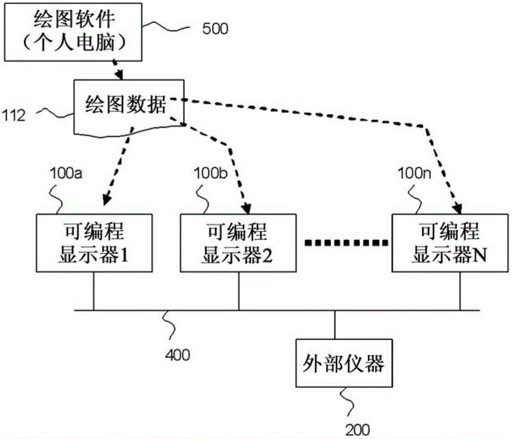
[0022] figure 1 It is a block diagram of the control system which consists of several programmable displays in Embodiment 1 for implementing this invention. exist figure 1 Among them, 100a-100n are programmable displays, and 112 is drawing data which prescribes the operation|movement of programmable displays 100a-100n. 200 is an external device such as a programmable controller. 400 is a communication path, and the external device 200 and programmable displays 100a-100n are mutually connected via the communication path 400.

[0023] 500 is a drawing data generating unit, which is drawing software stored in a personal computer (hereinafter simply referred to as “personal computer”), and the drawing data 112 is generated and changed using the drawing software 500 . When the drawing data 112 is generated and changed by the drawing software 500, the created and changed drawing data 112 is sent to the programmable display via a communication path newly installed on the program...

Embodiment 2

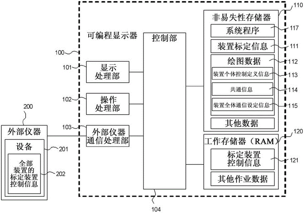
[0060] In Embodiment 1, the case where the device 201 as the first device is stored in the external device 200 has been described, but it is not limited to the configuration in which the device 201 is stored in the external device 200, such as Figure 10 As shown, the same effect can be achieved also by storing the device 201 in one of the first programmable displays 300 identified among the plurality of programmable displays as the second device.

[0061] In this Embodiment 2, the communication processing part 303 is provided in the programmable display 100 which is a 2nd programmable display, and the control part 104 The definition of the information 116 reads or writes in the device 201 memorize|stored in the 1st programmable display 300 through the communication processing part 303. The subsequent control procedure is the same as that described in Embodiment 1, so it is omitted here.


PUM


Abstract

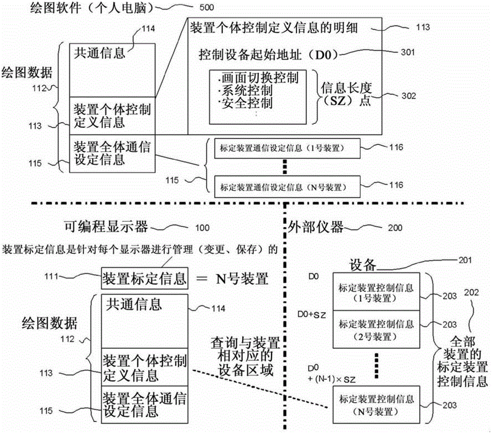
A control system including, a programmable display, and an external device that is connected to the programmable display, wherein the external device stores specific display control information into a first device for each display designation information in correspondence with the display designation information; and wherein the programmable display includes a first memory block that stores the display designation information and all display-specific communication setting information, and a control block that makes an access to the first device of the external device according to the display designation information and the all display-specific communication setting information, to thus acquire its specific display control information corresponding to the display designation information, that stores the acquired specific display control information into a second memory block, and that controls the programmable display according to the specific display control information stored in the second memory block.

Description

technical field [0001] The present invention relates to a control system of a programmable display with which drawing data can be shared, a programmable display and a drawing data generating unit thereof. Background technique [0002] In a conventional control system including a plurality of programmable displays, the following method is used. That is, when most of the drawing data of the respective programmable displays are common and some are different, by Drawing data is generated and managed by dividing and managing drawing data into common parts and unique parts on a programmable display, so that only the unique parts can be independently edited on each programmable display (for example, refer to Patent Document 1). [0003] Patent Document 1: Japanese Patent Application Laid-Open No. 8-263244 (page 3, image 3 ) SUMMARY OF THE INVENTION [0004] The existing control system is configured as above, so it is possible to solve the problem related to the horizontal expan...

Claims


Application Information

Patent Timeline
Patent Type & Authority Patents(China)
IPC IPC(8): G05B19/048G05B23/02
CPCG05B19/409G05B2219/36153Y02P90/02G05B23/02G05B19/048
Inventor 小荒健吾
Owner MITSUBISHI ELECTRIC CORP
Learn More