Drive motor for an electric vehicle

A technology for electric vehicles and electric motors, applied to electric vehicles, motors, vehicle components, etc., can solve problems such as reducing the centrifugal strength of motor rotors

Inactive Publication Date: 2012-11-14
NTN CORP
View PDF1 Cites 2 Cited by
  • Summary
  • Abstract
  • Description
  • Claims
  • Application Information

AI Technical Summary

Problems solved by technology

In the case of an IPM motor, contrary to the effect of "the permanent magnets are installed inside the rotor core, the scattering of the permanent magnets can be prevented", since the holes for the permanent magnets are opened inside the rotor core, it has The problem of reducing the centrifugal strength of the motor rotor

Method used


Image

  • Drive motor for an electric vehicle
  • Drive motor for an electric vehicle
  • Drive motor for an electric vehicle

Examples


Embodiment Construction

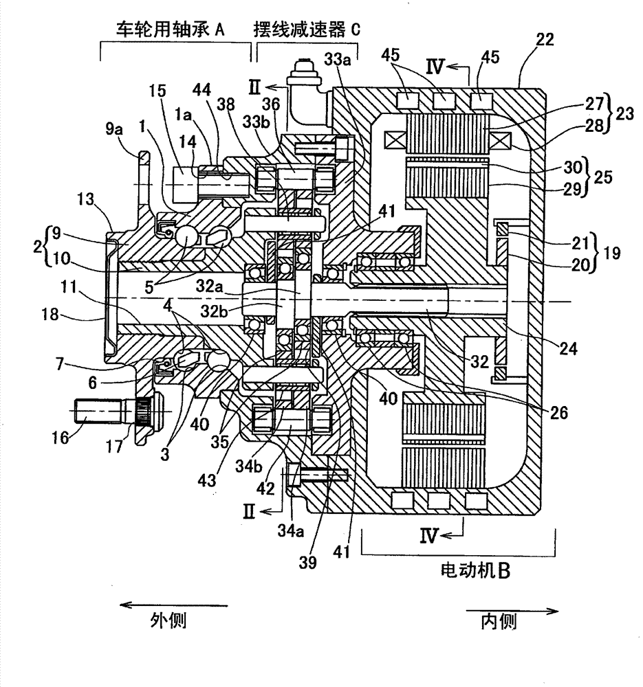
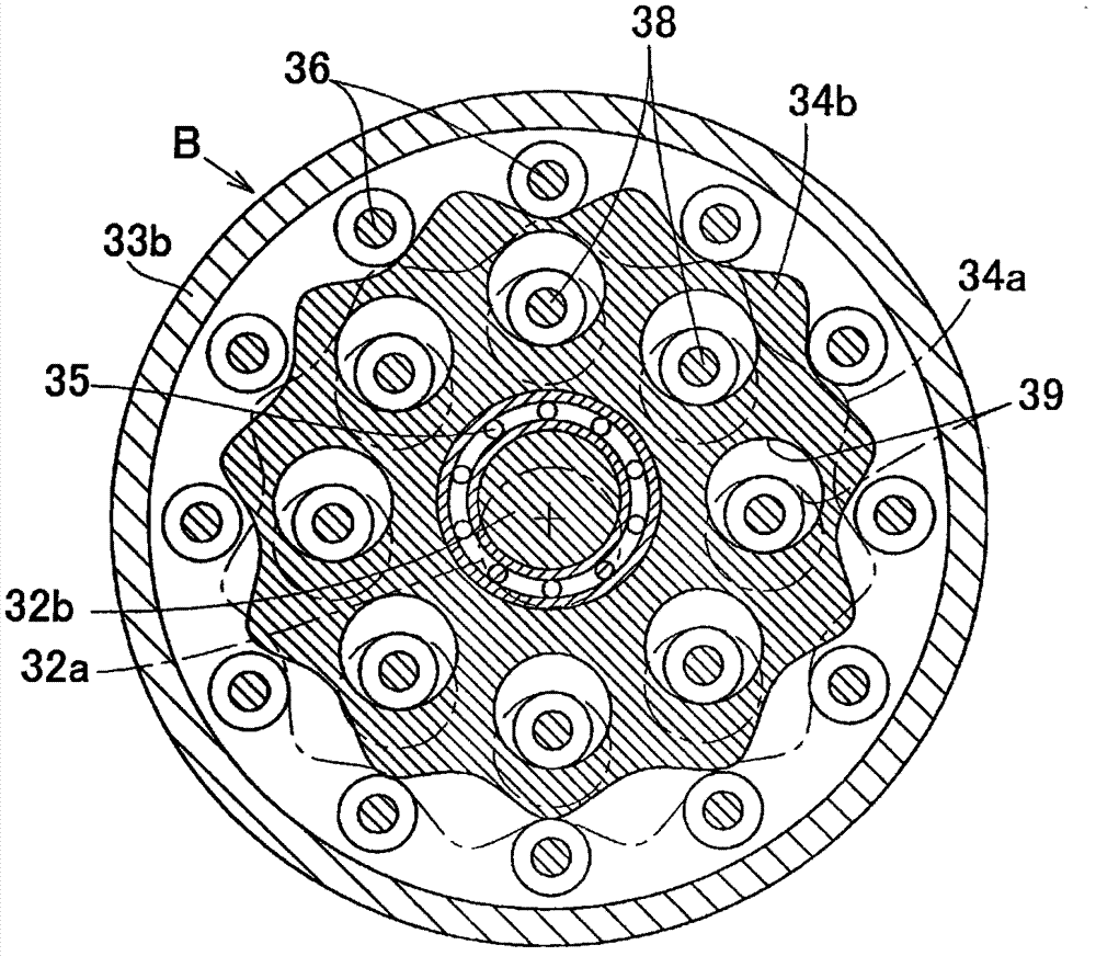
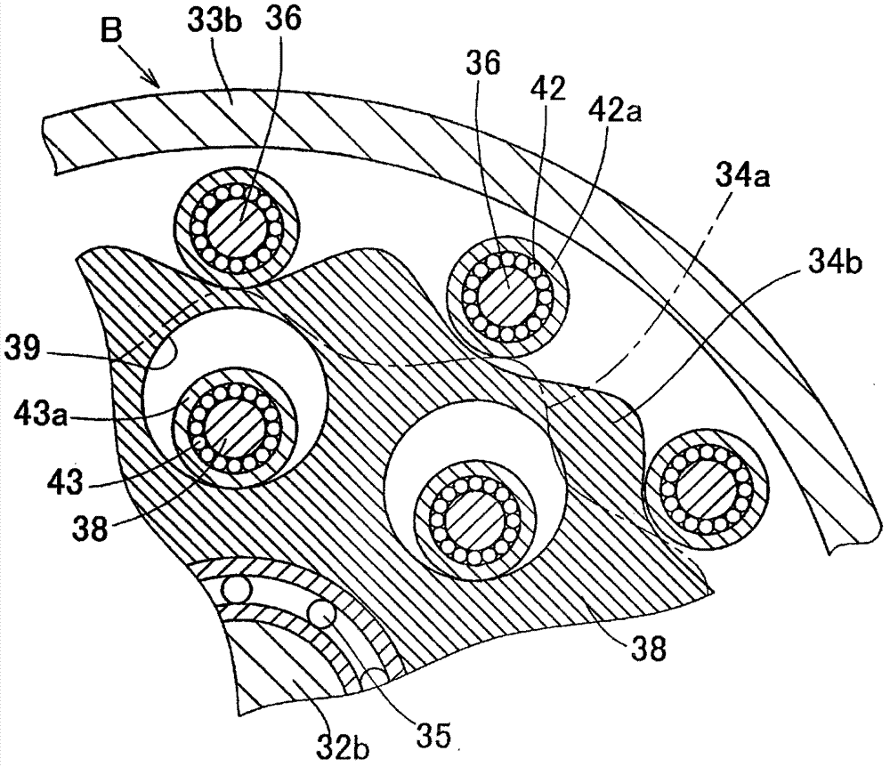
[0029] Figure 1 to Figure 4 The first embodiment of the present invention is shown. figure 1 It is a longitudinal cross-sectional view showing a wheel bearing device equipped with a driving motor of an electric vehicle according to this embodiment. This wheel bearing device is an inner wheel type motor built-in wheel bearing device, in which a speed reducer C is interposed between the wheel bearing A of the vehicle and the driving motor B of this embodiment, and is supported by the wheel bearing A. The hub of the driving wheel and the rotation output shaft 24 of the driving motor B are connected on the same axis. The speed reducer C is a cycloid speed reducer, which has a structure in which eccentric portions 32a, 32b are formed on the rotation input shaft 32 coaxially connected to the rotation output shaft 24 of the drive motor B, and Curved plates 34a, 34b are attached to the portions 32a, 32b via bearings 35, respectively, and the eccentric motion of the curved plates 34...


PUM


Abstract

The disclosed drive motor for an electric vehicle makes it possible, without increasing the diameter of a rotor in the motor, to stop the rotor from rotating with respect to a rotation output shaft. The disclosed drive motor is an IPM motor with a rotor (25) that comprises: a rotor core (29) with an inner surface that has a circular cross-section and fits around a rotation output shaft (24); and permanent magnets (30) disposed inside the rotor core (29). At angular positions near parts of permanent magnets (30) that are tilted towards the outer edge of the rotor core (29), the inner surface of the rotor core (29) and the outer surface of the rotation output shaft (24) are provided with non-circular sections (29a and 24a), with non-circular cross-sections, that constitute rotation-stopping means (31) that stop the rotor (25) from rotating with respect to the rotation output shaft (24).

Description

[0001] related application [0002] This application claims the priority of the application number of JP Japanese Patent Application No. 2010-047791 with the filing date on March 4, 2010, and uses it as the content which comprises a part of this application by referring to the whole. technical field [0003] The present invention relates to a drive motor for an electric vehicle, which is used as an in-wheel type motor built in a wheel of the vehicle, and the like. Background technique [0004] In an electric vehicle, failure of a motor for driving the vehicle used therein and a controller for controlling the motor can lead to a fatal situation, and therefore, these failures must be absolutely avoided from the viewpoint of reliability. In many cases, an IPM motor (implanted magnet synchronous motor) in which a permanent magnet is built into a rotor core portion of a motor rotor is used as a driving motor for the electric vehicle. In the case of an IPM motor, contrary to the ...

Claims


Application Information

Patent Timeline
Patent Type & Authority Applications(China)
IPC IPC(8): H02K1/28
CPCH02K1/30Y02T10/641H02K1/28Y02T10/64
Inventor 尾崎孝美牧野祐介冈田浩一
Owner NTN CORP
Why Eureka
Try Eureka